CART ASSEMBLY | 8 |
|
|
7
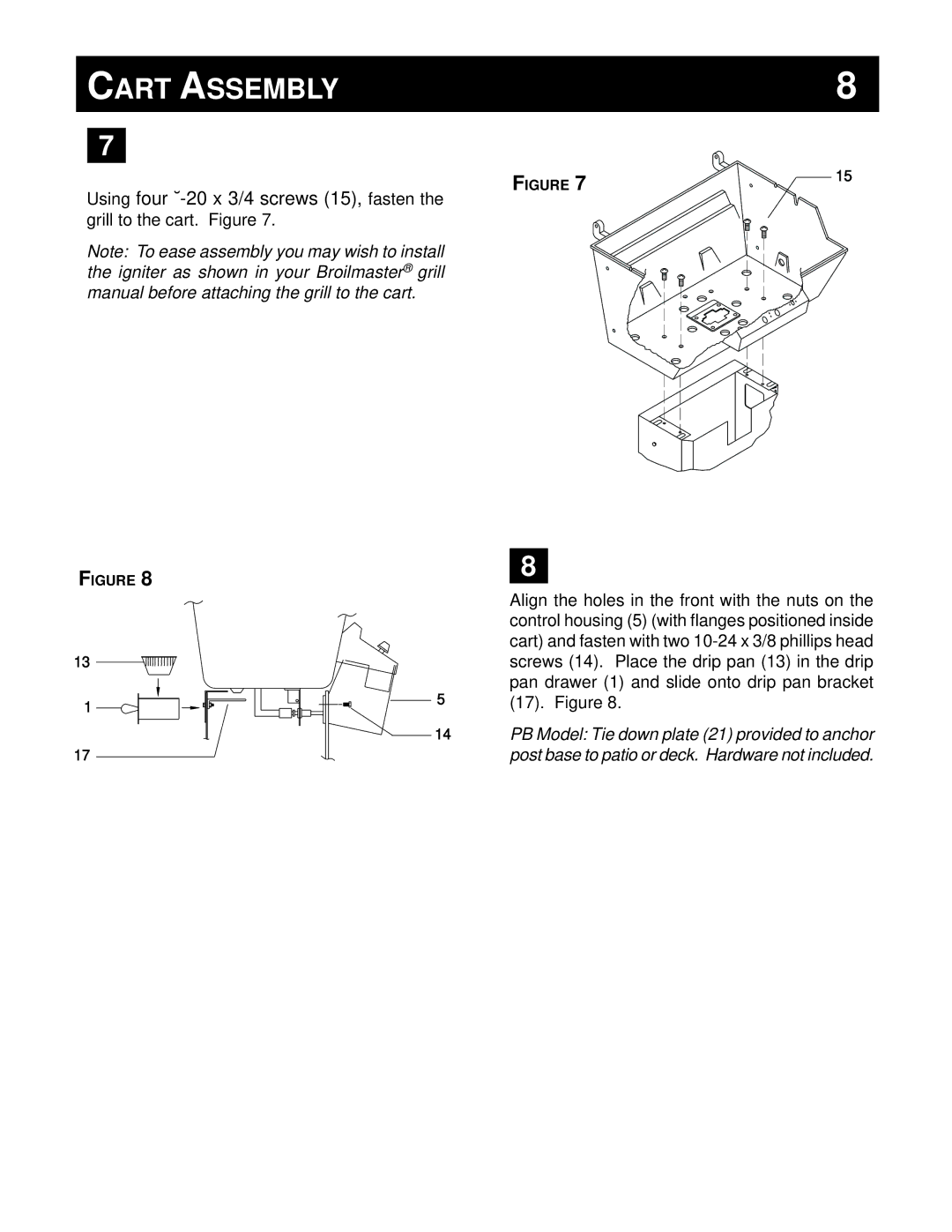
FIGURE 7 | 15 |
|
Using four
Note: To ease assembly you may wish to install the igniter as shown in your Broilmaster® grill manual before attaching the grill to the cart.
FIGURE 8
8
13
1
17
5
![]() 14
14
Align the holes in the front with the nuts on the control housing (5) (with flanges positioned inside cart) and fasten with two
PB Model: Tie down plate (21) provided to anchor post base to patio or deck. Hardware not included.