PATIO BASE POST PART LIST | 10 |
|
|
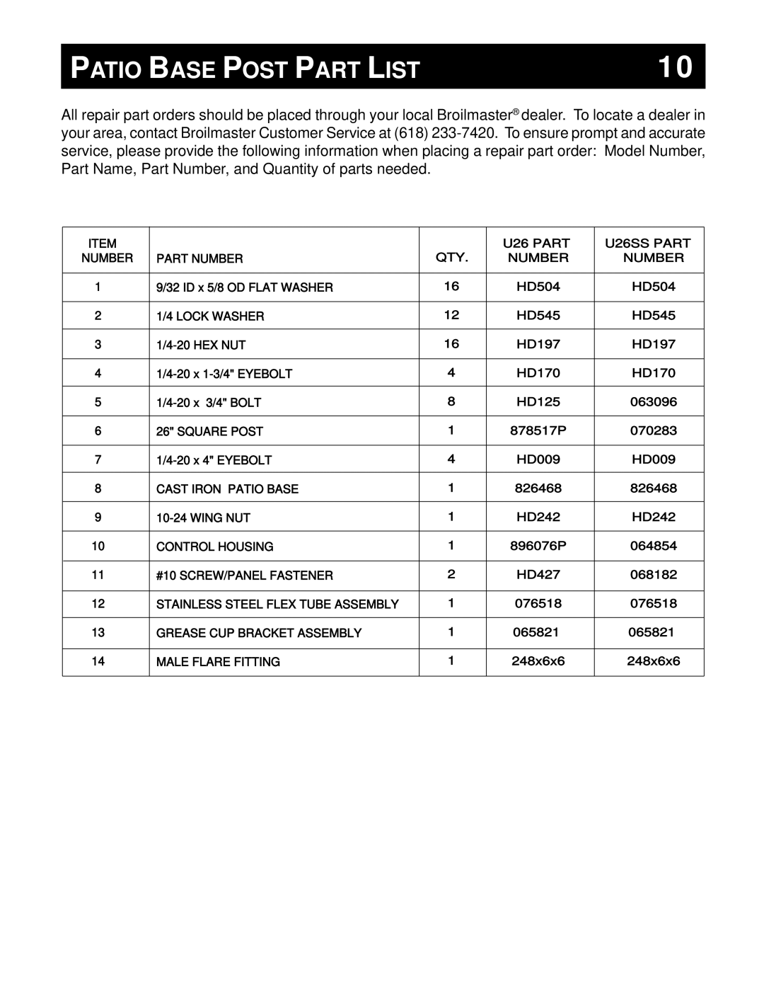
All repair part orders should be placed through your local Broilmaster® dealer. To locate a dealer in your area, contact Broilmaster Customer Service at (618)
ITEM
NUMBER
1
2
3
4
5
6
7
8
9
10
11
12
13
14
PART NUMBER | QTY. |
9/32 ID x 5/8 OD FLAT WASHER | 16 |
1/4 LOCK WASHER | 12 |
16 | |
4 | |
8 | |
26" SQUARE POST | 1 |
4 | |
CAST IRON PATIO BASE | 1 |
1 | |
CONTROL HOUSING | 1 |
#10 SCREW/PANEL FASTENER | 2 |
STAINLESS STEEL FLEX TUBE ASSEMBLY | 1 |
GREASE CUP BRACKET ASSEMBLY | 1 |
MALE FLARE FITTING | 1 |
U26 PART | U26SS PART |
NUMBER | NUMBER |
HD504 | HD504 |
HD545 | HD545 |
HD197 | HD197 |
HD170 | HD170 |
HD125 | 063096 |
878517P | 070283 |
HD009 | HD009 |
826468 | 826468 |
HD242 | HD242 |
896076P | 064854 |
HD427 | 068182 |
076518 | 076518 |
065821 | 065821 |
248x6x6 | 248x6x6 |