PATIO BASE POST ASSEMBLY | 12 |
|
|
4
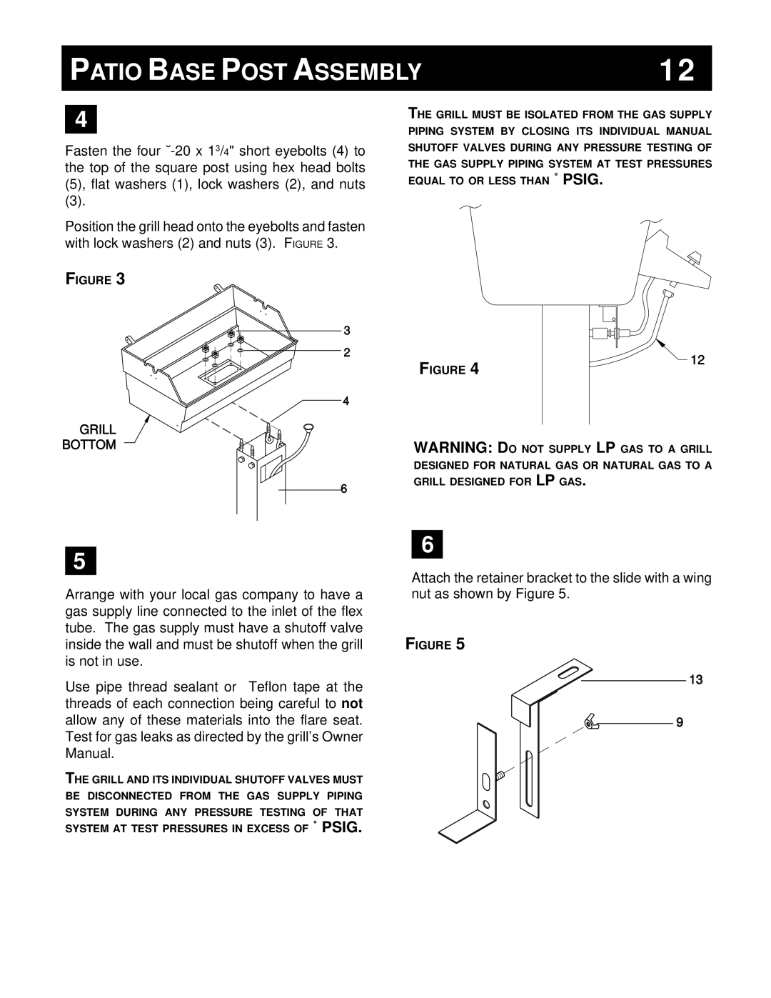
Fasten the four
(3).
Position the grill head onto the eyebolts and fasten with lock washers (2) and nuts (3). FIGURE 3.
FIGURE 3
3
THE GRILL MUST BE ISOLATED FROM THE GAS SUPPLY PIPING SYSTEM BY CLOSING ITS INDIVIDUAL MANUAL SHUTOFF VALVES DURING ANY PRESSURE TESTING OF THE GAS SUPPLY PIPING SYSTEM AT TEST PRESSURES EQUAL TO OR LESS THAN ˚ PSIG.
2
4
FIGURE 4
![]() 12
12
GRILL
BOTTOM
6
WARNING: DO NOT SUPPLY LP GAS TO A GRILL DESIGNED FOR NATURAL GAS OR NATURAL GAS TO A GRILL DESIGNED FOR LP GAS.
5
Arrange with your local gas company to have a gas supply line connected to the inlet of the flex tube. The gas supply must have a shutoff valve inside the wall and must be shutoff when the grill is not in use.
Use pipe thread sealant or Teflon tape at the threads of each connection being careful to not allow any of these materials into the flare seat. Test for gas leaks as directed by the grill’s Owner Manual.
THE GRILL AND ITS INDIVIDUAL SHUTOFF VALVES MUST BE DISCONNECTED FROM THE GAS SUPPLY PIPING
SYSTEM DURING ANY PRESSURE TESTING OF THAT SYSTEM AT TEST PRESSURES IN EXCESS OF ˚ PSIG.
6
Attach the retainer bracket to the slide with a wing nut as shown by Figure 5.
FIGURE 5
13
9