| 16 |
|
|
The U48 and P48
Verify that all parts listed in the exploded view of this product have been included before beginning this installation.
Recommended Tools:
•Two adjustable wrenches or a socket set
•A medium Phillips screwdriver
•Pipe thread sealer or Teflon tape (for gas connections)
•Soapy water solution (to test for leaks)
CAUTION: THE CONCRETE MIXTURE MUST NOT COVER THE GAS SUPPLY ENTRY HOLE ON THE POST.
THE GAS SUPPLY ENTRY HOLE (2" DIAMETER HOLE) IS LOCATED 18 3/4" FROM THE BOTTOM OF THE
POST.
Make a final alignment check with the level, and adjust as needed. Allow concrete to set (usually 24 hours).
2
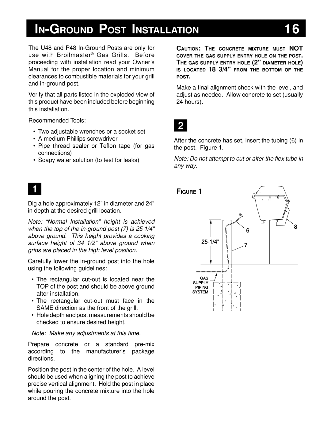
After the concrete has set, insert the tubing (6) in the post. Figure 1.
Note: Do not attempt to cut or alter the flex tube in any way.
1
Dig a hole approximately 12" in diameter and 24" in depth at the desired grill location.
Note: “Normal Installation” height is achieved when the top of the
Carefully lower the
•The rectangular
•The rectangular
•Hole depth and post measurements should be checked to ensure desired height.
Note: Make any adjustments at this time.
Prepare concrete or a standard
Position the post in the center of the hole. A level should be used when aligning the post to achieve precise vertical alignment. Hold the post in place while pouring the concrete mixture into the hole around the post.
FIGURE 1
GAS
SUPPLY
PIPING
SYSTEM
6
7
8