VI. GAS PIPING

Gas piping must be installed in accordance with national and local codes. Refer to current edition of NFGC. Canadian installations must be made in accordance with NSCNGPIC and all authorities having jurisdiction. Gas supply line should be a separate line running directly from meter to furnace, if possible. Refer to Table 3 for recommended gas pipe sizing. Risers must be used to connect to furnace and to meter. Support all gas piping with appropriate straps, hangers, etc. Use a minimum of 1 hanger every 6 ft. Joint compound (pipe dope) should be applied sparingly and only to male threads of joints. Pipe dope must be resistant to propane gas.

TABLE 3ÐMAXIMUM CAPACITY OF PIPE*

NOMINAL


LENGTH OF PIPE (FT)


IRON

INTERNAL


PIPE

DIAMETER


SIZE

(IN.)

10


20

30

40

50

(IN.)


1/2

0.622

175


120

97

82

73

3/4

0.824

360


250

200

170

151

1

1.049

680


465

375

320

285

1-1/4

1.380

1400


950

770

660

580

1-1/2

1.610

2100


1460

1180

990

900


*Cubic ft of gas per hr for gas pressures of 0.5 psig (14-in. wc) or less, and a pressure drop of 0.5-in. wc (based on a 0.60 specific gravity gas). Ref: Table 10-2 NFPA 54-1996.

CAUTION: Connect gas pipe to furnace using a backup wrench to avoid damaging gas controls.

WARNING: Gas valve shutoff switch MUST be facing forward or tilted upward. Failure to follow this warning

could result in property damage or death.

WARNING: Never purge a gas line into a combustion chamber. Never use matches, candles, flame, or other sources of ignition for purpose of checking leakage. Use a soap-and-water solution to check for leakage. A failure to follow this warning could result in fire, explosion, personal injury, or death.

WARNING: Use proper length of pipe to avoid stress on gas control manifold. Failure to follow this warning could result in a gas leak resulting in fire, explosion, personal injury, or death.

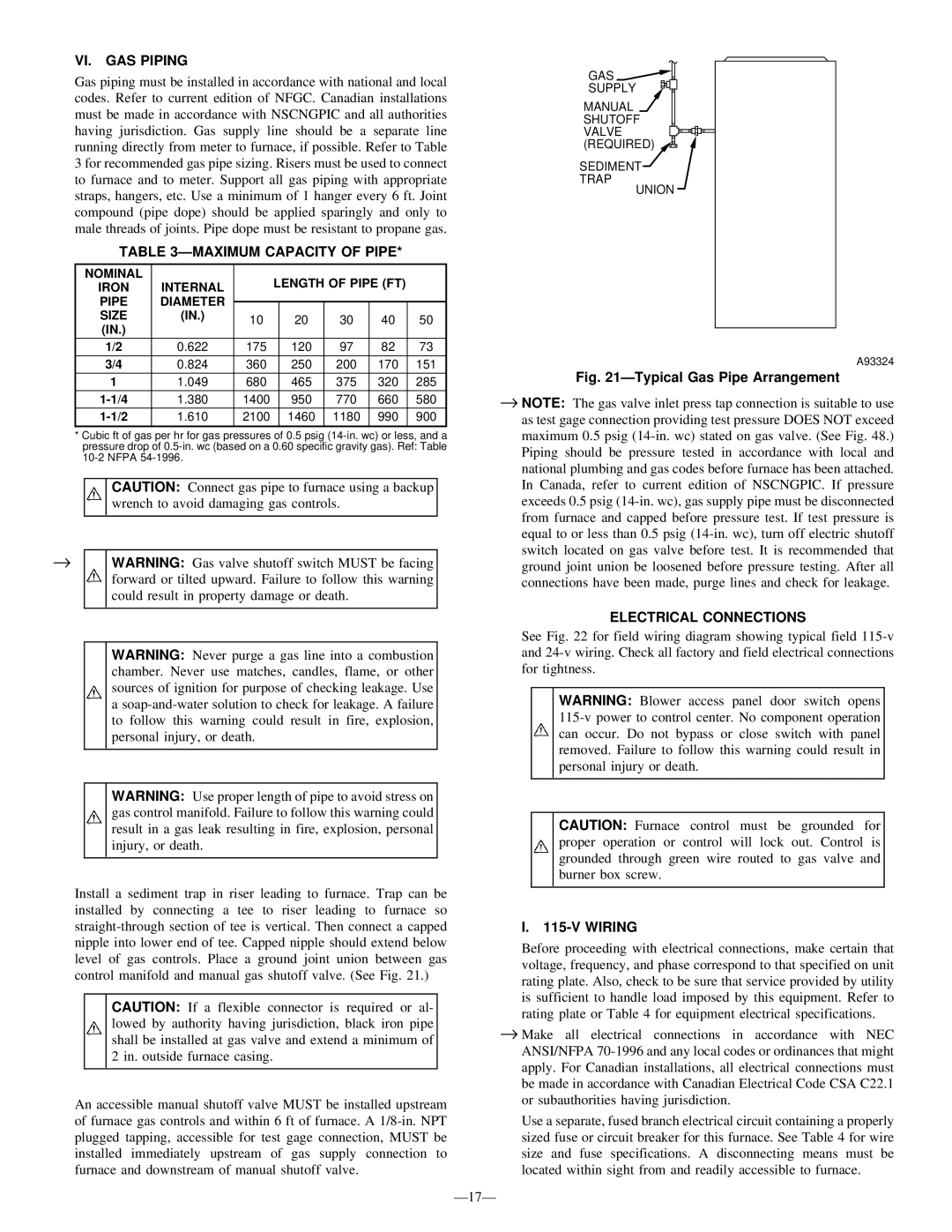
Install a sediment trap in riser leading to furnace. Trap can be installed by connecting a tee to riser leading to furnace so straight-through section of tee is vertical. Then connect a capped nipple into lower end of tee. Capped nipple should extend below level of gas controls. Place a ground joint union between gas control manifold and manual gas shutoff valve. (See Fig. 21.)

CAUTION: If a flexible connector is required or al- lowed by authority having jurisdiction, black iron pipe shall be installed at gas valve and extend a minimum of 2 in. outside furnace casing.

An accessible manual shutoff valve MUST be installed upstream of furnace gas controls and within 6 ft of furnace. A 1/8-in. NPT plugged tapping, accessible for test gage connection, MUST be installed immediately upstream of gas supply connection to furnace and downstream of manual shutoff valve.

GAS

SUPPLY

MANUAL

SHUTOFF

VALVE (REQUIRED)

SEDIMENT

TRAP

UNION

A93324

Fig. 21ÐTypical Gas Pipe Arrangement

NOTE: The gas valve inlet press tap connection is suitable to use as test gage connection providing test pressure DOES NOT exceed maximum 0.5 psig (14-in. wc) stated on gas valve. (See Fig. 48.) Piping should be pressure tested in accordance with local and national plumbing and gas codes before furnace has been attached. In Canada, refer to current edition of NSCNGPIC. If pressure exceeds 0.5 psig (14-in. wc), gas supply pipe must be disconnected from furnace and capped before pressure test. If test pressure is equal to or less than 0.5 psig (14-in. wc), turn off electric shutoff switch located on gas valve before test. It is recommended that ground joint union be loosened before pressure testing. After all connections have been made, purge lines and check for leakage.

ELECTRICAL CONNECTIONS

See Fig. 22 for field wiring diagram showing typical field 115-v and 24-v wiring. Check all factory and field electrical connections for tightness.

WARNING: Blower access panel door switch opens 115-v power to control center. No component operation can occur. Do not bypass or close switch with panel removed. Failure to follow this warning could result in personal injury or death.

CAUTION: Furnace control must be grounded for proper operation or control will lock out. Control is grounded through green wire routed to gas valve and burner box screw.

I.115-V WIRING

Before proceeding with electrical connections, make certain that voltage, frequency, and phase correspond to that specified on unit rating plate. Also, check to be sure that service provided by utility is sufficient to handle load imposed by this equipment. Refer to rating plate or Table 4 for equipment electrical specifications.

Make all electrical connections in accordance with NEC ANSI/NFPA 70-1996 and any local codes or ordinances that might apply. For Canadian installations, all electrical connections must be made in accordance with Canadian Electrical Code CSA C22.1 or subauthorities having jurisdiction.

Use a separate, fused branch electrical circuit containing a properly sized fuse or circuit breaker for this furnace. See Table 4 for wire size and fuse specifications. A disconnecting means must be located within sight from and readily accessible to furnace.

Ð17Ð

Page 17
Image 17
Bryant 355M-40-5, 355M-40-4 operating instructions VI. GAS Piping, Ðmaximum Capacity of Pipe, Electrical Connections, Wiring

355M-40-4, 355M-40-5 specifications

The Bryant 355M-40-5 and 355M-40-4 are innovative CNC cylindrical grinders designed to meet the demands of precision machining in various industrial applications. These machines stand out due to their robust construction, advanced technology, and versatile functionalities, which are critical for achieving high-quality grinding results.

One of the main features of the Bryant 355M-40-5 and 355M-40-4 is their precision grinding capability. With high spindle speeds and excellent rigidity, these grinders are engineered to deliver superior surface finishes even on complex geometries. The machines are equipped with advanced dressing systems that ensure consistent wheel profiles, enhancing performance and reducing cycle times.

The Bryant 355M-40-5 differentiates itself through its multi-axis capability, allowing for the grinding of intricate shapes and features without the need for extensive setup changes. Operators can easily program complex grinding sequences through the user-friendly interface, which supports both manual and automated operations. This flexibility is crucial in manufacturing environments that require quick turnaround times and adaptability to various workpieces.

Meanwhile, the Bryant 355M-40-4 focuses on efficiency and productivity, featuring a streamlined design that optimizes workflow. The machine is fitted with high-precision linear guides and ball screws, ensuring smooth and accurate movements during the grinding process. This results in minimal wear and tear, thereby extending the machine's lifespan and maintaining accuracy over time.

Key technologies incorporated into both models include state-of-the-art control systems that enable real-time monitoring and feedback during operations. This feature allows operators to make on-the-fly adjustments to optimize grinding parameters, leading to improved performance and reduced scrap rates. Additionally, the integration of automation solutions, such as robotic loading systems, enhances productivity by minimizing downtime and labor costs.

The Bryant 355M-40-5 and 355M-40-4 are built with durability in mind, utilizing high-strength materials that resist deformation and wear. Their thermal stability ensures consistent performance even under varying operating conditions, making them a reliable choice for high-volume production.

In summary, the Bryant 355M-40-5 and 355M-40-4 models are exemplary CNC cylindrical grinders that combine precision, efficiency, and advanced technology. Their features make them suitable for a wide range of grinding applications, from tool manufacturing to automotive components, ensuring that they remain competitive in the ever-evolving landscape of manufacturing technology.