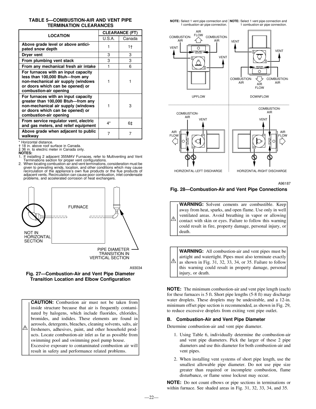
TABLE 5ÐCOMBUSTION-AIR AND VENT PIPE

TERMINATION CLEARANCES

LOCATION

CLEARANCE (FT)

U.S.A.

Canada


Above grade level or above antici-

1

pated snow depth


Dryer vent

3

3

From plumbing vent stack

3

3

From any mechanical fresh air intake

1

6

For furnaces with an input capacity


less than 100,000 BtuhÐfrom any


non-mechanical air supply (windows

1

1

or doors which can be opened) or


combustion-air opening


For furnaces with an input capacity


greater than 100,000 BtuhÐfrom any


non-mechanical air supply (windows

1

3

or doors which can be opened) or


combustion-air opening


From service regulator vent, electric

4*

and gas meters, and relief equipment


Above grade when adjacent to public

7

7

walkway


* Horizontal distance.

² 18 in. above roof surface in Canada.

³36 in. to electric meter in Canada only.

NOTES:

1. If installing 2 adjacent 355MAV Furnaces, refer to Multiventing and Vent Terminations section for proper vent configurations.

2. When locating combustion-air and vent terminations, consideration must be given to prevailing winds, location, and other conditions which may cause recirculation of the appliance's own flue products or the flue products of adjacent vents. Recirculation can cause poor combustion, inlet condensate problems, and accelerated corrosion of heat exchangers.

NOTE: Select 1 vent pipe connection and

NOTE: Select 1 vent pipe connection and

1 combustion-air pipe connection.

1 combustion-air pipe connection.

AIR


COMBUSTION- FLOW COMBUSTION-


AIR

AIR

VENT


VENT


VENT


VENT


COMBUSTION-

COMBUSTION-


AIR

AIR

AIR


FLOW


UPFLOW


DOWNFLOW


COMBUSTION-

COMBUSTION-


AIR


AIR


VENT


VENT


AIR


AIR

FLOW


FLOW

HORIZONTAL-LEFT DISCHARGE

HORIZONTAL-RIGHT DISCHARGE

A96187

Fig. 28ÐCombustion-Air and Vent Pipe Connections

NOT IN HORIZONTAL SECTION

FURNACE

PIPE DIAMETER

TRANSITION IN

VERTICAL SECTION

A93034

WARNING: Solvent cements are combustible. Keep away from heat, sparks, and open flame. Use only in well ventilated areas. Avoid breathing in vapor or allowing contact with skin or eyes. Failure to follow this warning could result in fire, property damage, personal injury, or death.

WARNING: All combustion-air and vent pipes must be airtight and watertight. Pipes must also terminate exactly as shown in Fig. 31, 32, 33, 34, or 35. Failure to follow this warning could result in property damage, personal

Fig. 27ÐCombustion-Air and Vent Pipe Diameter

Transition Location and Elbow Configuration

CAUTION: Combustion air must not be taken from inside structure because that air is frequently contami- nated by halogens, which include fluorides, chlorides, bromides, and iodides. These elements are found in aerosols, detergents, bleaches, cleaning solvents, salts, air fresheners, adhesives, paint, and other household prod- ucts. Locate combustion-air inlet as far as possible from swimming pool and swimming pool pump house.

Excessive exposure to contaminated combustion air will result in safety and performance related problems.

Ð22Ð

injury, or death.

NOTE: The minimum combustion-air and vent pipe length (each) for these furnaces is 5 ft. Short pipe lengths (5-8 ft) may discharge water droplets. These droplets may be undesirable, and a 12-in. minimum offset pipe section is recommended, as shown in Fig. 29, to reduce excessive droplets from exiting vent pipe outlet.

B.Combustion-Air and Vent Pipe Diameter

Determine combustion-air and vent pipe diameter.

1.Using Table 6, individually determine the combustion-air and vent pipe diameters. Pick the larger of these 2 pipe diameters and use this diameter for both combustion-air and vent pipes.

2.When installing vent systems of short pipe length, use the smallest allowable pipe diameter. Do not use pipe size greater than required or incomplete combustion, flame disturbance, or flame sense lockout may occur.

NOTE: Do not count elbows or pipe sections in terminations or within furnace. See shaded areas in Fig. 31, 32, 33, 34, and 35.

Page 22
Image 22
Bryant 355M-40-4 ÐCOMBUSTION-AIR and Vent Pipe Termination Clearances, Combustion-Air and Vent Pipe Diameter, Walkway

355M-40-4, 355M-40-5 specifications

The Bryant 355M-40-5 and 355M-40-4 are innovative CNC cylindrical grinders designed to meet the demands of precision machining in various industrial applications. These machines stand out due to their robust construction, advanced technology, and versatile functionalities, which are critical for achieving high-quality grinding results.

One of the main features of the Bryant 355M-40-5 and 355M-40-4 is their precision grinding capability. With high spindle speeds and excellent rigidity, these grinders are engineered to deliver superior surface finishes even on complex geometries. The machines are equipped with advanced dressing systems that ensure consistent wheel profiles, enhancing performance and reducing cycle times.

The Bryant 355M-40-5 differentiates itself through its multi-axis capability, allowing for the grinding of intricate shapes and features without the need for extensive setup changes. Operators can easily program complex grinding sequences through the user-friendly interface, which supports both manual and automated operations. This flexibility is crucial in manufacturing environments that require quick turnaround times and adaptability to various workpieces.

Meanwhile, the Bryant 355M-40-4 focuses on efficiency and productivity, featuring a streamlined design that optimizes workflow. The machine is fitted with high-precision linear guides and ball screws, ensuring smooth and accurate movements during the grinding process. This results in minimal wear and tear, thereby extending the machine's lifespan and maintaining accuracy over time.

Key technologies incorporated into both models include state-of-the-art control systems that enable real-time monitoring and feedback during operations. This feature allows operators to make on-the-fly adjustments to optimize grinding parameters, leading to improved performance and reduced scrap rates. Additionally, the integration of automation solutions, such as robotic loading systems, enhances productivity by minimizing downtime and labor costs.

The Bryant 355M-40-5 and 355M-40-4 are built with durability in mind, utilizing high-strength materials that resist deformation and wear. Their thermal stability ensures consistent performance even under varying operating conditions, making them a reliable choice for high-volume production.

In summary, the Bryant 355M-40-5 and 355M-40-4 models are exemplary CNC cylindrical grinders that combine precision, efficiency, and advanced technology. Their features make them suitable for a wide range of grinding applications, from tool manufacturing to automotive components, ensuring that they remain competitive in the ever-evolving landscape of manufacturing technology.