IV. PURGE GAS LINES

If not previously done, purge the lines after all connections have been made and check for leaks.

WARNING: Never purge a gas line into a combustion chamber. Never use matches, candles, flame, or other sources of ignition for the purpose of checking leakage. Use a soap-and-water solution to check for leakage. Failure to follow this warning could result in fire, explosion, personal injury, or death.

V.ADJUSTMENTS

A.Set Gas Input Rate

Furnace gas input rate on rating plate is for installations at altitudes up to 2000 ft.

In the U.S.A., the input rating for altitudes above 2000 ft must be reduced by 2 percent for each 1000 ft above sea level.

In Canada, the input rating must be derated by 5 percent for altitudes of 2000 ft to 4500 ft above sea level.

Furnace input rate must be within ±2 percent of input on furnace rating plate.

1.Determine natural gas orifice size and manifold pressure for correct input.

a.Obtain yearly heat value average (at installed altitude) from local gas supplier.

b.Obtain yearly specific gravity average from local gas supplier.

c.Verify furnace model. Table 12 can only be used for model 355MAV Furnaces.

d.Find installation altitude in Table 12.

NOTE: For Canada altitudes of 2000 to 4500 ft, use U.S.A. altitudes of 2001 to 3000 ft in Table 12.

e.Find closest natural gas heat value and specific gravity in Table 12.

f.Follow heat value and specific gravity lines to point of intersection to find orifice size and low- and high-heat manifold pressure settings for proper operation.

EXAMPLE: (0Ð2000 ft altitude) Heating value = 1050 Btu/cu ft Specific gravity = 0.62 Therefore: Orifice No. 45

Manifold pressure: 3.6-in. wc for high heat 1.5-in. wc for low heat

*Furnace is shipped with No. 45 orifices. In this example, all main burner orifices are the correct size and do not need to be changed to obtain proper input rate.

g.Check and verify burner orifice size in furnace. NEVER ASSUME ORIFICE SIZE; ALWAYS CHECK AND VERIFY.

2.Adjust manifold pressure to obtain input rate.

a.Remove burner enclosure front.

NOTE: Manifold pressure MUST always be measured with the burner box cover REMOVED.

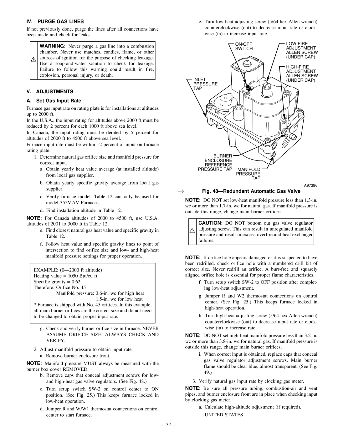
b. Remove caps that conceal adjustment screws for low- and high-heat gas valve regulators. (See Fig. 48.)

c. Turn setup switch SW-2 on control center to ON position. (See Fig. 25.) This keeps furnace locked in low-heat operation.

d.Jumper R and W/W1 thermostat connections on control center to start furnace.

e.Turn low-heat adjusting screw (5/64 hex Allen wrench) counterclockwise (out) to decrease input rate or clock- wise (in) to increase input rate.


ON/OFF

LOW-FIRE


SWITCH

ADJUSTMENT


ALLEN SCREW


(UNDER CAP)


HIGH-FIRE


ADJUSTMENT

INLET


ALLEN SCREW

F


O

(UNDER CAP)

PRESSURE

F


TAP

ON


BURNER

ENCLOSURE

REFERENCE

PRESSURE TAP MANIFOLD

PRESSURE

TAP

A97386

Fig. 48ÐRedundant Automatic Gas Valve

NOTE: DO NOT set low-heat manifold pressure less than 1.3-in. wc or more than 1.7-in. wc for natural gas. If manifold pressure is outside this range, change main burner orifices.

CAUTION: DO NOT bottom out gas valve regulator adjusting screw. This can result in unregulated manifold pressure and result in excess overfire and heat exchanger failures.

NOTE: If orifice hole appears damaged or it is suspected to have been redrilled, check orifice hole with a numbered drill bit of correct size. Never redrill an orifice. A burr-free and squarely aligned orifice hole is essential for proper flame characteristics.

f.Turn setup switch SW-2 to OFF position after complet- ing low-heat adjustment.

g.Jumper R and W2 thermostat connections on control center. (See Fig. 25.) This keeps furnace locked in high-heat operation.

h.Turn high-heat adjusting screw (5/64 hex Allen wrench) counterclockwise (out) to decrease input rate or clock- wise (in) to increase rate.

NOTE: DO NOT set high-heat manifold pressure less than 3.2-in. wc or more than 3.8-in. wc for natural gas. If manifold pressure is outside this range, change main burner orifices.

i.When correct input is obtained, replace caps that conceal gas valve regulator adjustment screws. Main burner flame should be clear blue, almost transparent. (See Fig. 49.)

3.Verify natural gas input rate by clocking gas meter.

NOTE: Be sure all pressure tubing, combustion-air and vent pipes, and burner enclosure front are in place when checking input by clocking gas meter.

a.Calculate high-altitude adjustment (if required).

UNITED STATES

Ð37Ð

Page 37
Image 37
Bryant 355M-40-5 IV. Purge GAS Lines, Adjustments, Set Gas Input Rate, → ÐRedundant Automatic Gas Valve, United States

355M-40-4, 355M-40-5 specifications

The Bryant 355M-40-5 and 355M-40-4 are innovative CNC cylindrical grinders designed to meet the demands of precision machining in various industrial applications. These machines stand out due to their robust construction, advanced technology, and versatile functionalities, which are critical for achieving high-quality grinding results.

One of the main features of the Bryant 355M-40-5 and 355M-40-4 is their precision grinding capability. With high spindle speeds and excellent rigidity, these grinders are engineered to deliver superior surface finishes even on complex geometries. The machines are equipped with advanced dressing systems that ensure consistent wheel profiles, enhancing performance and reducing cycle times.

The Bryant 355M-40-5 differentiates itself through its multi-axis capability, allowing for the grinding of intricate shapes and features without the need for extensive setup changes. Operators can easily program complex grinding sequences through the user-friendly interface, which supports both manual and automated operations. This flexibility is crucial in manufacturing environments that require quick turnaround times and adaptability to various workpieces.

Meanwhile, the Bryant 355M-40-4 focuses on efficiency and productivity, featuring a streamlined design that optimizes workflow. The machine is fitted with high-precision linear guides and ball screws, ensuring smooth and accurate movements during the grinding process. This results in minimal wear and tear, thereby extending the machine's lifespan and maintaining accuracy over time.

Key technologies incorporated into both models include state-of-the-art control systems that enable real-time monitoring and feedback during operations. This feature allows operators to make on-the-fly adjustments to optimize grinding parameters, leading to improved performance and reduced scrap rates. Additionally, the integration of automation solutions, such as robotic loading systems, enhances productivity by minimizing downtime and labor costs.

The Bryant 355M-40-5 and 355M-40-4 are built with durability in mind, utilizing high-strength materials that resist deformation and wear. Their thermal stability ensures consistent performance even under varying operating conditions, making them a reliable choice for high-volume production.

In summary, the Bryant 355M-40-5 and 355M-40-4 models are exemplary CNC cylindrical grinders that combine precision, efficiency, and advanced technology. Their features make them suitable for a wide range of grinding applications, from tool manufacturing to automotive components, ensuring that they remain competitive in the ever-evolving landscape of manufacturing technology.