Ð2Ð

1412"

TYP

114"

1"

26 1516"


28 12"


26 14"


AIRFLOW


26 1516"


24 12"


26 14"


22 516"


A


22

5

16"


916"


1316"


2-IN. COMBUSTION-


13/16"

D

13/16"


19"


CONDENSATE DRAIN


TYP


58"


AIR CONN


OUTLET


OUTLET


TRAP LOCATION


(DOWNFLOW &


CONDENSATE DRAIN

2-IN. COMBUSTION-


HORIZONTAL LEFT)


TRAP LOCATION


AIR CONN


78-IN. DIA


(DOWNFLOW &


516"


12-IN. DIA

POWER CONN


HORIZONTAL RIGHT)

12-IN. DIA


OR ALTERNATE


GAS CONN


12-IN. DIA GAS CONN

GAS CONN


2-IN. VENT CONN


78-IN. DIA


33 14"


POWER CONN


TYP


1


32 58"


12-IN. DIA


2-IN. DIA THERMOSTAT


TYP


ENTRY


THERMOSTAT ENTRY


78-IN. DIA


30 1316"


22 1116"


30

1

2"


39

7

8


ACCESSORY


29 1116"


2-IN. VENT CONN


"


POWER ENTRY


27 58" TYP


CONDENSATE


22 1116"


DRAIN TRAP


27 916"


LOCATION


TYP


(ALTERNATE

24

12"


UPFLOW)


SIDE INLET


SIDE INLET


17 516"


18 14"


9 716"


TYP


1"


INLET


CONDENSATE

22 14" TYP

716"


CONDENSATE


23 14" TYP


11/16"

E

11/16"

DRAIN LOCATION


DRAIN LOCATION


SIDE INLET


(UPFLOW)


(UPFLOW)


DIMPLE LOCATORS

24 316"


1116"


26 1516" TYP


BOTTOM INLET


FOR HORIZONTAL


HANGING


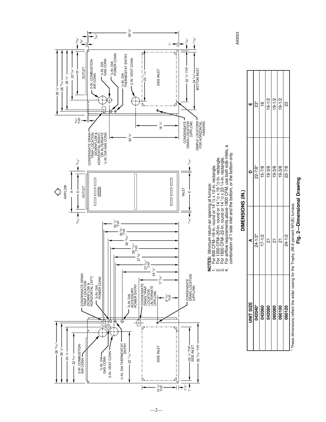
NOTES: Minimum return-air opening at furnace:

1.For 800 CFM--16-In. round or 14 1/2 x 12-In. rectangle.

2.For 1200 CFM--20-In. round or 14 1/2 x 19 1/2-In. rectangle.

3.For 1600 CFM--22-In. round or 14 1/2 x 23 1/4-In. rectangle.

4.For airflow requirements above 1800 CFM, use both side inlets, a combination of 1 side inlet and the bottom, or the bottom only.

A93023

DIMENSIONS (IN.)

UNIT SIZE

A

D

E

042040*

24-1/2*

22-7/8*

23*

042060

17-1/2

15-7/8

16

042080

21

19-3/8

19-1/2

060080

21

19-3/8

19-1/2

060100

21

19-3/8

19-1/2

060120

24-1/2

22-7/8

23

* These dimensions reflect the wider casing for the Trophy (96.6 percent AFUE) furnace.

Fig. 2ÐDimensional Drawing

Page 2
Image 2
Bryant 355M-40-4, 355M-40-5 operating instructions Ð2Ð, Dimensions, Unit Size

355M-40-4, 355M-40-5 specifications

The Bryant 355M-40-5 and 355M-40-4 are innovative CNC cylindrical grinders designed to meet the demands of precision machining in various industrial applications. These machines stand out due to their robust construction, advanced technology, and versatile functionalities, which are critical for achieving high-quality grinding results.

One of the main features of the Bryant 355M-40-5 and 355M-40-4 is their precision grinding capability. With high spindle speeds and excellent rigidity, these grinders are engineered to deliver superior surface finishes even on complex geometries. The machines are equipped with advanced dressing systems that ensure consistent wheel profiles, enhancing performance and reducing cycle times.

The Bryant 355M-40-5 differentiates itself through its multi-axis capability, allowing for the grinding of intricate shapes and features without the need for extensive setup changes. Operators can easily program complex grinding sequences through the user-friendly interface, which supports both manual and automated operations. This flexibility is crucial in manufacturing environments that require quick turnaround times and adaptability to various workpieces.

Meanwhile, the Bryant 355M-40-4 focuses on efficiency and productivity, featuring a streamlined design that optimizes workflow. The machine is fitted with high-precision linear guides and ball screws, ensuring smooth and accurate movements during the grinding process. This results in minimal wear and tear, thereby extending the machine's lifespan and maintaining accuracy over time.

Key technologies incorporated into both models include state-of-the-art control systems that enable real-time monitoring and feedback during operations. This feature allows operators to make on-the-fly adjustments to optimize grinding parameters, leading to improved performance and reduced scrap rates. Additionally, the integration of automation solutions, such as robotic loading systems, enhances productivity by minimizing downtime and labor costs.

The Bryant 355M-40-5 and 355M-40-4 are built with durability in mind, utilizing high-strength materials that resist deformation and wear. Their thermal stability ensures consistent performance even under varying operating conditions, making them a reliable choice for high-volume production.

In summary, the Bryant 355M-40-5 and 355M-40-4 models are exemplary CNC cylindrical grinders that combine precision, efficiency, and advanced technology. Their features make them suitable for a wide range of grinding applications, from tool manufacturing to automotive components, ensuring that they remain competitive in the ever-evolving landscape of manufacturing technology.