2-SPEED

VARIABLE

2-SPEED AIR


SPEED

THERMOSTAT

THERMOSTAT

CONDITIONER


R


R


R


C


C


C


G


G


W2


W/W1


W2


Y2


Y/Y2


Y2


E


W3


L


L


Y1


Y1


A94302

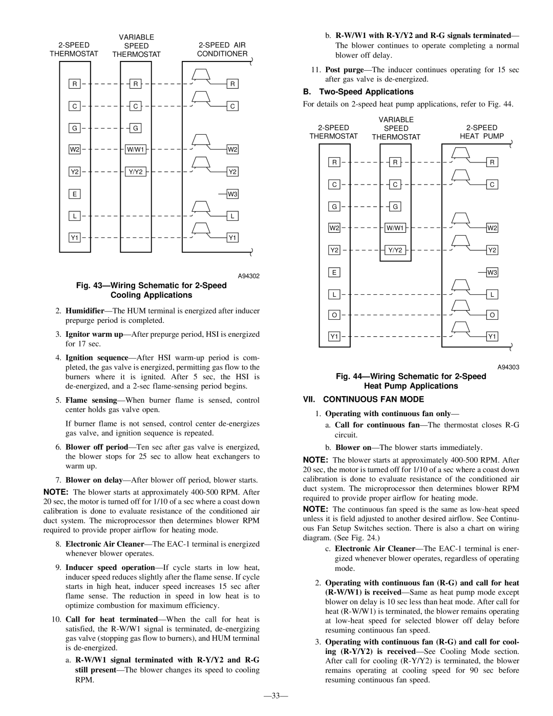
Fig. 43ÐWiring Schematic for 2-Speed

Cooling Applications

2.HumidifierÐThe HUM terminal is energized after inducer prepurge period is completed.

3.Ignitor warm upÐAfter prepurge period, HSI is energized for 17 sec.

4.Ignition sequenceÐAfter HSI warm-up period is com- pleted, the gas valve is energized, permitting gas flow to the burners where it is ignited. After 5 sec, the HSI is de-energized, and a 2-sec flame-sensing period begins.

5.Flame sensingÐWhen burner flame is sensed, control center holds gas valve open.

If burner flame is not sensed, control center de-energizes gas valve, and ignition sequence is repeated.

6.Blower off periodÐTen sec after gas valve is energized, the blower stops for 25 sec to allow heat exchangers to warm up.

7.Blower on delayÐAfter blower off period, blower starts.

NOTE: The blower starts at approximately 400-500 RPM. After 20 sec, the motor is turned off for 1/10 of a sec where a coast down calibration is done to evaluate resistance of the conditioned air duct system. The microprocessor then determines blower RPM required to provide proper airflow for heating mode.

8.Electronic Air CleanerÐThe EAC-1 terminal is energized whenever blower operates.

9.Inducer speed operationÐIf cycle starts in low heat, inducer speed reduces slightly after the flame sense. If cycle starts in high heat, inducer speed increases 15 sec after flame sense. The reduction in speed in low heat is to optimize combustion for maximum efficiency.

10.Call for heat terminatedÐWhen the call for heat is satisfied, the R-W/W1 signal is terminated, de-energizing gas valve (stopping gas flow to burners), and HUM terminal is de-energized.

a.R-W/W1 signal terminated with R-Y/Y2 and R-G still presentÐThe blower changes its speed to cooling RPM.

Ð33Ð

b.R-W/W1 with R-Y/Y2 and R-G signals terminatedÐ The blower continues to operate completing a normal blower off delay.

11.Post purgeÐThe inducer continues operating for 15 sec after gas valve is de-energized.

B.Two-Speed Applications

For details on 2-speed heat pump applications, refer to Fig. 44.

2-SPEED

VARIABLE

2-SPEED

SPEED

THERMOSTAT

THERMOSTAT

HEAT PUMP

R

R

R

C

C

C

G

G


W2

W/W1

W2

Y2

Y/Y2

Y2

E


W3

L


L

O


O

Y1


Y1

A94303

Fig. 44ÐWiring Schematic for 2-Speed

Heat Pump Applications

VII. CONTINUOUS FAN MODE

1.Operating with continuous fan onlyÐ

a.Call for continuous fanÐThe thermostat closes R-G circuit.

b.Blower onÐThe blower starts immediately.

NOTE: The blower starts at approximately 400-500 RPM. After 20 sec, the motor is turned off for 1/10 of a sec where a coast down calibration is done to evaluate resistance of the conditioned air duct system. The microprocessor then determines blower RPM required to provide proper airflow for heating mode.

NOTE: The continuous fan speed is the same as low-heat speed unless it is field adjusted to another desired airflow. See Continu- ous Fan Setup Switches section. There is also a chart on wiring diagram. (See Fig. 24.)

c.Electronic Air CleanerÐThe EAC-1 terminal is ener- gized whenever blower operates, regardless of operating mode.

2.Operating with continuous fan (R-G) and call for heat (R-W/W1) is receivedÐSame as heat pump mode except blower on delay is 10 sec less than heat mode. After call for heat (R-W/W1) is terminated, the blower remains operating at low-heat speed for selected blower off delay before resuming continuous fan speed.

3.Operating with continuous fan (R-G) and call for cool- ing (R-Y/Y2) is receivedÐSee Cooling Mode section. After call for cooling (R-Y/Y2) is terminated, the blower remains operating at cooling speed for 90 sec before resuming continuous fan speed.

Page 33
Image 33
Bryant 355M-40-5, 355M-40-4 ÐWiring Schematic for 2-Speed Cooling Applications, VII. Continuous FAN Mode

355M-40-4, 355M-40-5 specifications

The Bryant 355M-40-5 and 355M-40-4 are innovative CNC cylindrical grinders designed to meet the demands of precision machining in various industrial applications. These machines stand out due to their robust construction, advanced technology, and versatile functionalities, which are critical for achieving high-quality grinding results.

One of the main features of the Bryant 355M-40-5 and 355M-40-4 is their precision grinding capability. With high spindle speeds and excellent rigidity, these grinders are engineered to deliver superior surface finishes even on complex geometries. The machines are equipped with advanced dressing systems that ensure consistent wheel profiles, enhancing performance and reducing cycle times.

The Bryant 355M-40-5 differentiates itself through its multi-axis capability, allowing for the grinding of intricate shapes and features without the need for extensive setup changes. Operators can easily program complex grinding sequences through the user-friendly interface, which supports both manual and automated operations. This flexibility is crucial in manufacturing environments that require quick turnaround times and adaptability to various workpieces.

Meanwhile, the Bryant 355M-40-4 focuses on efficiency and productivity, featuring a streamlined design that optimizes workflow. The machine is fitted with high-precision linear guides and ball screws, ensuring smooth and accurate movements during the grinding process. This results in minimal wear and tear, thereby extending the machine's lifespan and maintaining accuracy over time.

Key technologies incorporated into both models include state-of-the-art control systems that enable real-time monitoring and feedback during operations. This feature allows operators to make on-the-fly adjustments to optimize grinding parameters, leading to improved performance and reduced scrap rates. Additionally, the integration of automation solutions, such as robotic loading systems, enhances productivity by minimizing downtime and labor costs.

The Bryant 355M-40-5 and 355M-40-4 are built with durability in mind, utilizing high-strength materials that resist deformation and wear. Their thermal stability ensures consistent performance even under varying operating conditions, making them a reliable choice for high-volume production.

In summary, the Bryant 355M-40-5 and 355M-40-4 models are exemplary CNC cylindrical grinders that combine precision, efficiency, and advanced technology. Their features make them suitable for a wide range of grinding applications, from tool manufacturing to automotive components, ensuring that they remain competitive in the ever-evolving landscape of manufacturing technology.