8 WIRING DIAGRAMS cont .
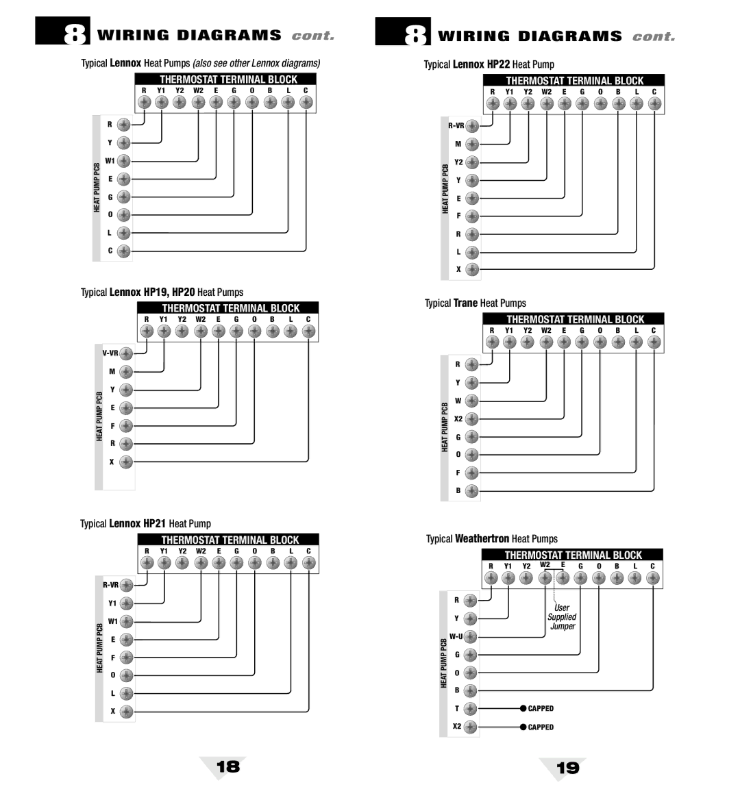
Typical Lennox Heat Pumps (also see other Lennox diagrams)
THERMOSTAT TERMINAL BLOCK
R | Y1 | Y2 | W2 | E | G | O | B | L | C |
| R | |
| Y | |
PCB | W1 | |
E | ||
PUMP | ||
G | ||
HEAT | ||
O | ||
| ||
| L | |
| C |
Typical Lennox HP19, HP20 Heat Pumps
THERMOSTAT TERMINAL BLOCK
R Y1 Y2 W2 E G O B L C
![]()
![]()
| M | |
PCB | Y | |
E | ||
PUMP | ||
F | ||
HEAT | ||
R | ||
| ||
| X |
Typical Lennox HP21 Heat Pump
THERMOSTAT TERMINAL BLOCK
R Y1 Y2 W2 E G O B L C
![]()
| Y1 | |
PCB | W1 | |
E | ||
PUMP | ||
F | ||
HEAT | ||
O | ||
| ||
| L | |
| X |
8 WIRING DIAGRAMS cont .
Typical Lennox HP22 Heat Pump
THERMOSTAT TERMINAL BLOCK
| R | Y1 | Y2 | W2 | E | G | O | B | L | C |
|
|
|
|
|
|
|
|
|
| |
| M |
|
|
|
|
|
|
|
|
|
PCB | Y2 |
|
|
|
|
|
|
|
|
|
Y |
|
|
|
|
|
|
|
|
| |
PUMP |
|
|
|
|
|
|
|
|
| |
E |
|
|
|
|
|
|
|
|
| |
HEAT |
|
|
|
|
|
|
|
|
| |
F |
|
|
|
|
|
|
|
|
| |
|
|
|
|
|
|
|
|
|
| |
| R |
|
|
|
|
|
|
|
|
|
| L |
|
|
|
|
|
|
|
|
|
| X |
|
|
|
|
|
|
|
|
|
Typical Trane Heat Pumps
THERMOSTAT TERMINAL BLOCK
R Y1 Y2 W2 E G O B L C
| R | |
| Y | |
PCB | W | |
X2 | ||
PUMP | ||
G | ||
HEAT | ||
O | ||
| ||
| F | |
| B |
Typical Weathertron Heat Pumps
THERMOSTAT TERMINAL BLOCK
R | Y1 | Y2 | W2 | E | G | O | B | L | C |
| R | User |
|
| |
| Y | Supplied |
|
| Jumper |
PCB |
| |
G |
| |
PUMP |
| |
O |
| |
HEAT |
| |
B |
| |
|
| |
| T | CAPPED |
| X2 | CAPPED |
18 | 19 |
