6 ADDITIONAL
OPERATION FEATURES cont ..
6.5Compressor Protection cont.
NOTE: The installer can reset the thermostat and bypass the compressor protection features by pressing the RESET button. This will erase all entered programs, current time of day, day of week and other user settings and should only be used during installation for testing purposes or to reset a thermostat to regain normal operation. This will return all Thermostat settings to their default values. The user will have to
6.6High Temperature Safety Switch
While the thermostat is in the HEAT mode of operation (selector switch in the HEAT position), the thermostat will mechanically
WARNING! Read BEFORE proceeding
Press RESET button using a paper clip or a small pencil tip. This will reset the thermostat and return all settings to their default values. Verify your thermostat is controlling your system, see Testing Your New Thermostat. If the problems still persist, call a professional service technician immediately to verify proper system operation.
6.7Changing Fahrenheit (°F) to Celsius (°C)
1.Release the front thermostat body from the rear thermostat body by pressing the release latch on the bottom of the thermostat.
2.Gently separate the two thermostat halves and turn the front thermostat body over exposing the rear view of the circuit board.
3.Locate the internal ˚F / ˚C switch on the circuit board.
4.Using your fingers, gently flip the switch towards the preferred temperature ˚F / ˚C scale.
5.Reattach the front thermostat body by locating the top mounting lugs and swinging the thermostat down until the release latch locks.
6.Press the RESET button on the front of the thermostat using a paper clip or a small pencil tip. This will register the new temperature scale default.
NOTE: Resetting the thermostat by pressing the RESET button will erase all entered programs, current time of day, day of week and other user settings.
This will return all Thermostat settings to their default values. Changing ˚F / ˚C temperature scale default should be done prior to installation and before any programming to avoid loss during reset step.
6.8Low Battery Detection and Replacement
NOTE: This thermostat requires 24 Volt AC power for normal operation and control of the heating or cooling systems. This thermostat also requires two (2) properly installed "AA" alkaline batteries to retain user settings and programs in the event of loss of AC Power due to power outage or rolling blackouts.
This thermostat is equipped with a low battery detection feature that constantly monitors the
6 ADDITIONAL
OPERATION FEATURES cont .
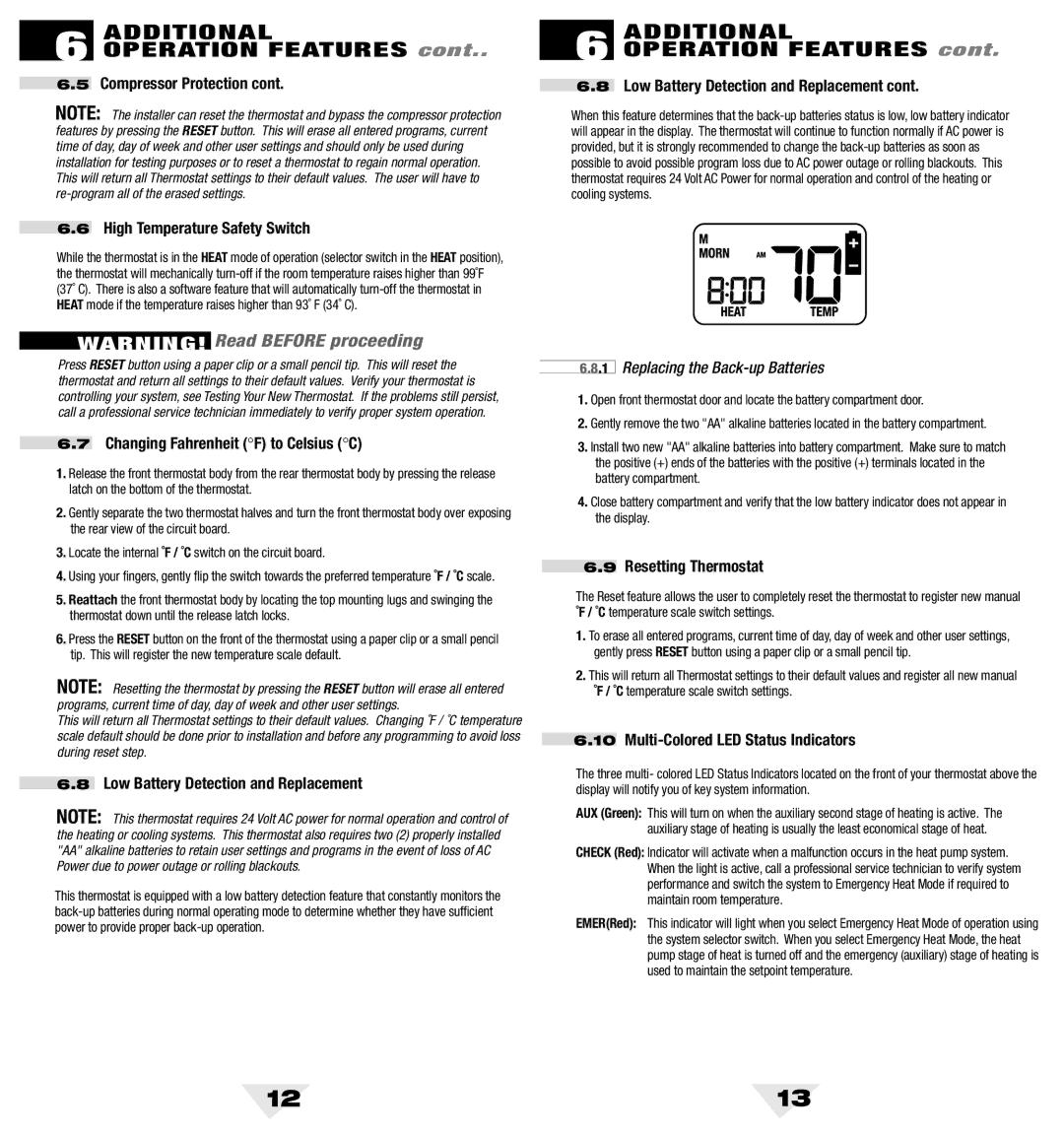
6.8Low Battery Detection and Replacement cont.
When this feature determines that the
6.8.1 Replacing the Back-up Batteries
1.Open front thermostat door and locate the battery compartment door.
2.Gently remove the two "AA" alkaline batteries located in the battery compartment.
3.Install two new "AA" alkaline batteries into battery compartment. Make sure to match the positive (+) ends of the batteries with the positive (+) terminals located in the battery compartment.
4.Close battery compartment and verify that the low battery indicator does not appear in the display.
6.9Resetting Thermostat
The Reset feature allows the user to completely reset the thermostat to register new manual ˚F / ˚C temperature scale switch settings.
1.To erase all entered programs, current time of day, day of week and other user settings, gently press RESET button using a paper clip or a small pencil tip.
2.This will return all Thermostat settings to their default values and register all new manual ˚F / ˚C temperature scale switch settings.
6.10Multi-Colored LED Status Indicators
The three multi- colored LED Status Indicators located on the front of your thermostat above the display will notify you of key system information.
AUX (Green): This will turn on when the auxiliary second stage of heating is active. The auxiliary stage of heating is usually the least economical stage of heat.
CHECK (Red): Indicator will activate when a malfunction occurs in the heat pump system. When the light is active, call a professional service technician to verify system performance and switch the system to Emergency Heat Mode if required to maintain room temperature.
EMER(Red): This indicator will light when you select Emergency Heat Mode of operation using the system selector switch. When you select Emergency Heat Mode, the heat pump stage of heat is turned off and the emergency (auxiliary) stage of heating is used to maintain the setpoint temperature.
12 | 13 |