3 INSTALLATION cont .
3.2Installing Your New Thermostat cont.
7.Mark placement of mounting holes as appropriate and drill using a 3/16" drill bit.
8.Gently tap supplied plastic anchors into the holes in the wall.
9.Place the thermostat rear body (mounting plate) against the wall in the desired location making sure the mounting holes are aligned as appropriate and the thermostat wires are properly inserting through opening in middle of rear body.
10.Fasten the rear body (mounting plate) to wall using supplied screws.
11.Connect wires to quick wiring terminal block as appropriate using the new terminal designations. Refer to Wiring Diagram section of this manual if required for assistance.
12.Make sure all of the wire connections are secure and are not touching any other terminal to prevent electrical shorts and potential damage to the thermostat.
13.Attach front body of thermostat to rear body of thermostat being careful to align the terminal pins on the front body with the terminal block on the rear body.
14.Open front thermostat door and open battery compartment door.
15.Install two new "AA" alkaline batteries into battery compartment. Make sure to locate the positive (+) ends of the batteries and match them with the positive (+) terminals located in the battery compartment.
16.Close battery compartment.
17.Restore system power so you can test installation.
4 TESTING YOUR NEW THERMOSTAT
WARNING! Read BEFORE Testing
•Do not short (or jumper) across terminals on the gas valve or at the heating or cooling system control board to test the thermostat installation. This could damage the thermostat and void the warranty.
•Do not select COOL mode of operation if the outside temperature is below 50˚ F (10˚ C). This could possibly damage the controlled cooling system & may cause personal injury.
•This thermostat includes an automatic compressor protection feature to avoid potential damage to the cooling system from short cycling. This thermostat automatically provides a
NOTE: Test your thermostat prior to programming any user settings. Pressing the RESET button will erase any user entries for time of day, day of week, option settings and programming if previously programmed. This will return all user settings and return them to their default values. Remember, this will erase all programs entered by the user.
4 TESTING YOUR
NEW THERMOSTAT cont .
1.Place the system switch in the HEAT position.
2.Press the ![]() button on the keypad until the setpoint temperature setting is a minimum of 3 degrees higher than the current room temperature. The heating system should start within several seconds. The fan may not turn on immediately due to the heating system
button on the keypad until the setpoint temperature setting is a minimum of 3 degrees higher than the current room temperature. The heating system should start within several seconds. The fan may not turn on immediately due to the heating system
3.Place the system switch in the OFF position. The heating system should stop within several seconds.
4.Wait 5 minutes for the automatic compressor short cycle protection period to expire, or press the RESET button to bypass this feature for initial testing purposes. Pressing the RESET button will erase any user entries for time of day, day of week, option settings & programming if previously programmed.
5.Place the system switch in the COOL position.
6.Press the ![]() button on the keypad until the setpoint temperature is a minimum of 3 degrees lower than the current room temperature.
button on the keypad until the setpoint temperature is a minimum of 3 degrees lower than the current room temperature.
7.The cooling system should start within several seconds. Place the system switch in the OFF position. The cooling system should stop within 90 seconds (dependent on the setting of the Residual Cooling Fan Feature).
8.Place the fan switch in the ON position. The system blower should start.
9.Place the fan switch in the AUTO position. The system blower should stop.
5 PROGRAMMING
5.1Default Thermostat Settings
Function | Status After Reset |
Operation Mode | Normal Operating Mode |
Temperature Hold | Permanent and Temporary Hold Cleared |
Clock | 12:00 pm, Monday |
Room Temperature | 70˚ F (21.0˚ C), to be renewed within |
| 5 seconds |
Setpoint Temperature | According to system switch: |
| 62˚ F (17.0˚ C) for Heat, |
| Emergency Heat and Off |
| 85˚ F (29.0˚ C) for Cool |
Temperature Scale | ˚F or ˚C dependent on switch setting |
Operating Program | DAY program, Monday |
Low Battery Warning | Off, to be renewed within 5 seconds |
AC Interrupted Warning | Off, to be renewed within 5 seconds |
First Stage Differential | 1˚ F (0.5˚ C) |
Second Stage Differential | 2˚ F (1.0˚ C) |
Residual Cooling | 60 Seconds |
Short Cycle Protection Timer | Reset |
Efficient Recovery Mode | Reset |
Output Relays | Off |
5.2Setting Current Time of Day and Day of Week
NOTE: It is important for you to set the current time of day (note AM/PM indicator in display), and the current day of week correctly to avoid problems with program execution.
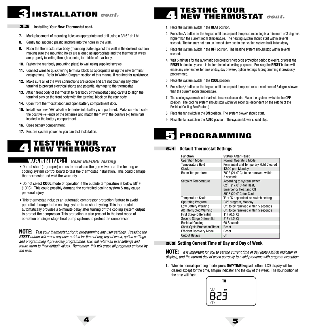
1.When in normal operating mode, press DAY/TIME keypad button. LCD display will be cleared except for the time, am/pm indicator and the day of the week. The hour portion of the time will flash.
4 | 5 |