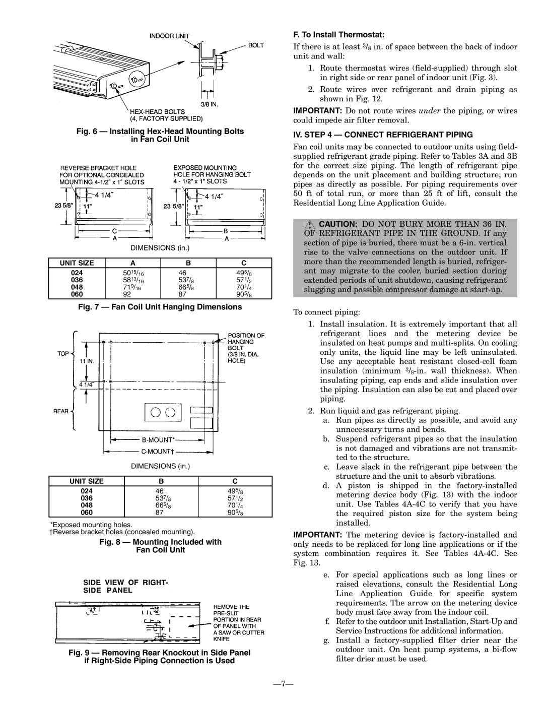
Fig. 6 — Installing Hex-Head Mounting Bolts
in Fan Coil Unit
DIMENSIONS (in.)
UNIT SIZE | A | B | C |
024 | 5015/16 | 46 | 495/8 |
036 | 5813/16 | 537/8 | 571/2 |
048 | 719/16 | 665/8 | 701/4 |
060 | 92 | 87 | 905/8 |
Fig. 7 — Fan Coil Unit Hanging Dimensions
DIMENSIONS (in.)
UNIT SIZE | B | C |
024 | 46 | 495/8 |
036 | 537/8 | 571/2 |
048 | 665/8 | 701/4 |
060 | 87 | 905/8 |
*Exposed mounting holes.
†Reverse bracket holes (concealed mounting).
Fig. 8 — Mounting Included with
Fan Coil Unit
Fig. 9 — Removing Rear Knockout in Side Panel
if Right-Side Piping Connection is Used
F. To Install Thermostat:
If there is at least 3/8 in. of space between the back of indoor unit and wall:
1.Route thermostat wires
2.Route wires over refrigerant and drain piping as shown in Fig. 12.
IMPORTANT: Do not route wires under the piping, or wires could impede air filter removal.
IV. STEP 4 — CONNECT REFRIGERANT PIPING
Fan coil units may be connected to outdoor units using field- supplied refrigerant grade piping. Refer to Tables 3A and 3B for the correct size piping. The length of refrigerant pipe depends on the unit placement and building structure; run pipes as directly as possible. For piping requirements over 50 ft of total run, or more than 25 ft of lift, consult the Residential Long Line Application Guide.
![]() CAUTION: DO NOT BURY MORE THAN 36 IN. OF REFRIGERANT PIPE IN THE GROUND. If any section of pipe is buried, there must be a
CAUTION: DO NOT BURY MORE THAN 36 IN. OF REFRIGERANT PIPE IN THE GROUND. If any section of pipe is buried, there must be a
To connect piping:
1.Install insulation. It is extremely important that all refrigerant lines and the metering device be insulated on heat pumps and
2.Run liquid and gas refrigerant piping.
a.Run pipes as directly as possible, and avoid any unnecessary turns and bends.
b.Suspend refrigerant pipes so that the insulation is not damaged and vibrations are not transmit- ted to the structure.
c.Leave slack in the refrigerant pipe between the structure and the unit to absorb vibrations.
d.A piston is shipped in the
IMPORTANT: The metering device is
e.For special applications such as long lines or raised elevations, consult the Residential Long Line Application Guide for specific system requirements. The arrow on the metering device body must face away from the indoor coil.
f.Refer to the outdoor unit Installation,
g.Install a