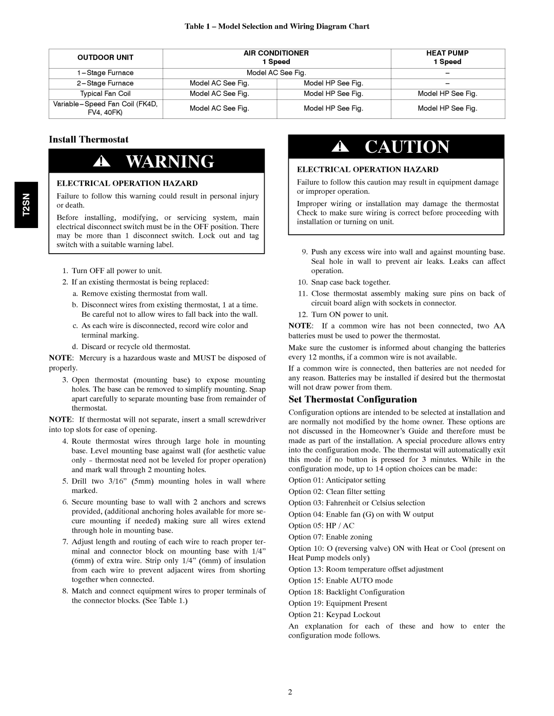
T2SNAC01, T2SNHP01 specifications
The Bryant T2SNHP01 and T2SNAC01 heat pump and air conditioner systems are designed to provide efficient heating and cooling solutions for residential environments. These systems represent Bryant's commitment to quality, durability, and energy efficiency, making them excellent choices for homeowners seeking reliable climate control.The Bryant T2SNHP01 is a high-efficiency heat pump system, which can provide both heating and cooling. It features advanced two-stage heating and cooling capabilities, ensuring balanced temperature control and consistent comfort. This model employs a variable-speed compressor, which allows it to adjust its output based on the home's specific requirements. This adaptability not only enhances comfort levels but also leads to significant energy savings by operating efficiently across varying conditions.
One of the standout features of the T2SNHP01 is its SEER (Seasonal Energy Efficiency Ratio) rating. With ratings as high as 16, this heat pump can significantly reduce energy consumption compared to lower-rated systems, leading to lower utility bills. The system operates quietly as well, thanks to its insulated compressor and fan design, which minimizes sound levels for a more pleasant home environment.
On the other hand, the Bryant T2SNAC01 serves as a highly efficient air conditioning unit designed to maximize cooling performance. Similar to its heat pump counterpart, the T2SNAC01 utilizes two-stage cooling. This dual cooling capability allows for optimal performance during both extreme temperatures and more moderate weather conditions. Like the T2SNHP01, this model also boasts impressive SEER ratings, offering efficiency that meets or exceeds industry standards.
Both systems incorporate the latest in eco-friendly refrigerant technology, using R-410A refrigerant, which is known for its lower environmental impact compared to older refrigerants. Additionally, both units are built with durable materials aimed at withstanding various weather conditions, ensuring longevity and reliability.
Another key characteristic is the smart technology integration available in both models. Homeowners can take advantage of Bryant's Smart Thermostat compatibility, allowing for remote control and programming via smartphones, enhancing user convenience and control over home climate.
In summary, the Bryant T2SNHP01 and T2SNAC01 provide efficient, reliable heating and cooling solutions. With their high SEER ratings, advanced technologies, eco-friendly refrigerants, and smart capabilities, these systems are well-suited for homeowners who prioritize comfort and energy savings in their climate control choices.

