CEZF, CDBC specifications
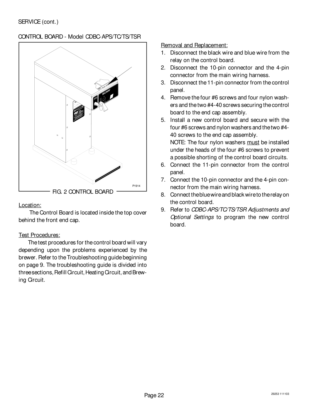
The Bunn CEZF and CDBC are two popular commercial coffee brewers offered by Bunn, a leader in the coffee equipment industry. Both models are designed to meet the demands of high-traffic settings such as cafes, restaurants, and other foodservice establishments. They combine advanced technology with user-friendly features to ensure consistent, high-quality coffee with minimal effort.The Bunn CEZF model is known for its easy-to-use design and efficiency. One of its standout features is the "Digital Brewer" control, which allows operators to adjust brewing parameters such as brew time and water temperature. This level of customization enables baristas to consistently create the perfect cup of coffee tailored to their specific blends. Furthermore, the CEZF has a unique "intelligent" warming plate that maintains the optimal serving temperature without over-extraction, ensuring that each cup of coffee remains flavorful.
On the other hand, the Bunn CDBC incorporates a dual brewing capacity that allows for larger batches of coffee to be made simultaneously. This feature is particularly beneficial in high-demand environments where quick service is essential. The CDBC also utilizes a patented brew control technology, enabling users to select their brew strength with just a few button presses. This flexibility is complemented by its high-performance heating element, which heats water rapidly, ensuring that coffee is brewed at the ideal temperature for optimal extraction.
Both models are equipped with a large water reservoir, ensuring a continuous supply of hot water for brewing. They also feature high-quality stainless steel constructions that enhance durability and make cleaning easier. The intuitive interface on both models simplifies operation, with clear instructions that allow even novice users to brew exceptional coffee right away.
In terms of safety, both the CEZF and CDBC are designed with auto shut-off features and integrated safety protocols, minimizing the risk of overheating and ensuring a secure brewing environment.
Overall, the Bunn CEZF and CDBC are excellent choices for any commercial kitchen or café looking to serve high-quality coffee efficiently. Their advanced features, durability, and ease of use make them top contenders in the commercial brewing category.

