APPENDIX C – Gas Piping
ASSURE GAS PIPING IS LEAK FREE AND OF PROPER SIZE and type for the
connected load.
SHUT OFF MAIN GAS SUPPLY prior to
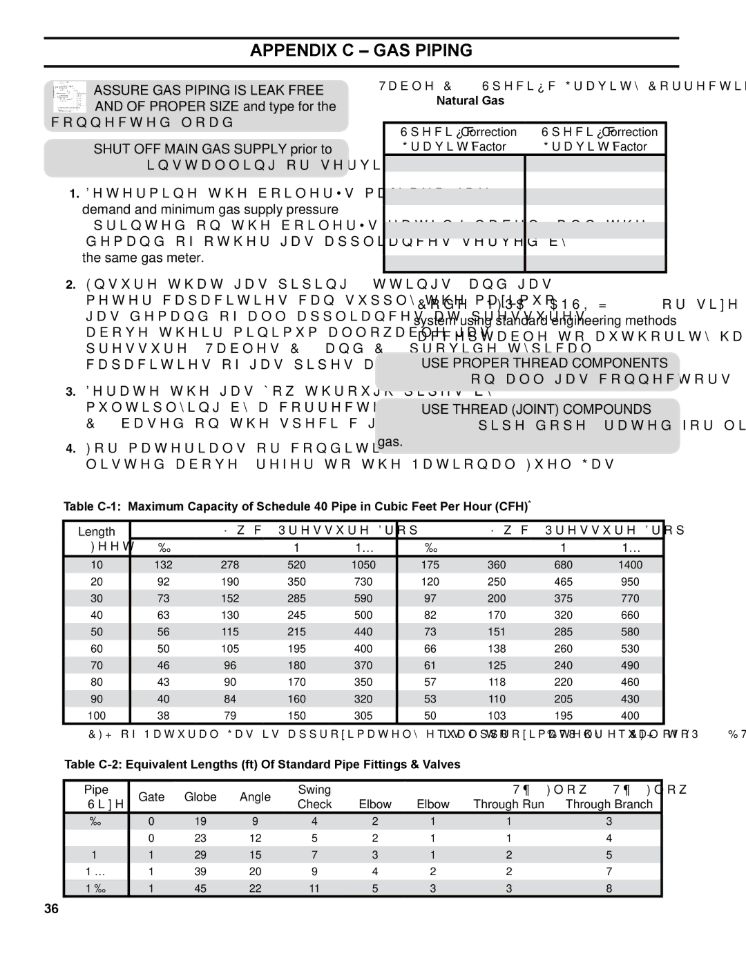
Table
Natural Gas
Specific Correction Specific Correction
Gravity Factor Gravity Factor
installing or servicing boiler gas piping.
1. | Determine the boiler’s maximum gas |
| demand and minimum gas supply pressure |
| (printed on the boiler’s rating label) and the |
| demand of other gas appliances served by |
| the same gas meter. |
2. | Ensure that gas piping, fittings, and gas |
0.501.10
0.551.04
0.601.00
0.650.96
0.700.93
0.750.90
0.800.87
0.850.81
0.900.82
1.000.78
1.100.74
1.200.71
1.300.68
1.400.66
meter capacities can supply the maximum |
gas demand of all appliances at pressures |
above their minimum allowable gas |
pressure. Tables |
capacities of gas pipes and fittings. |
3. Derate the gas flow through pipes by |
multiplying by a correction factor in Table |
4. For materials or conditions other than those |
listed above, refer to the National Fuel Gas |
Code, NFPA54/ANSI Z223.1, or size the system using standard engineering methods acceptable to authority having jurisdiction.
USE PROPER THREAD COMPONENTS on all gas connectors.
USE THREAD (JOINT) COMPOUNDS (pipe dope) rated for liquefied petroleum
gas.
Table
Length |
| 0.3” w.c. Pressure Drop |
|
| 0.5” w.c. Pressure Drop |
| ||
(Feet) | ½ | ¾ | 1 | 1¼ | ½ | ¾ | 1 | 1¼ |
10 | 132 | 278 | 520 | 1050 | 175 | 360 | 680 | 1400 |
20 | 92 | 190 | 350 | 730 | 120 | 250 | 465 | 950 |
30 | 73 | 152 | 285 | 590 | 97 | 200 | 375 | 770 |
40 | 63 | 130 | 245 | 500 | 82 | 170 | 320 | 660 |
50 | 56 | 115 | 215 | 440 | 73 | 151 | 285 | 580 |
60 | 50 | 105 | 195 | 400 | 66 | 138 | 260 | 530 |
70 | 46 | 96 | 180 | 370 | 61 | 125 | 240 | 490 |
80 | 43 | 90 | 170 | 350 | 57 | 118 | 220 | 460 |
90 | 40 | 84 | 160 | 320 | 53 | 110 | 205 | 430 |
100 | 38 | 79 | 150 | 305 | 50 | 103 | 195 | 400 |
*1 CFH of Natural Gas is approximately equal to 1000 BTU/hr; 1 CFH of LP is approximately equal to 2500 BTU/hr.
Table
Pipe | Gate | Globe | Angle | Swing | 90° | 45° | 90° ‘T’, Flow | 90° ‘T’, Flow | |
Size | Check | Elbow | Elbow | Through Run | Through Branch | ||||
|
|
| |||||||
½” | 0 | 19 | 9 | 4 | 2 | 1 | 1 | 3 | |
¾” | 0 | 23 | 12 | 5 | 2 | 1 | 1 | 4 | |
1” | 1 | 29 | 15 | 7 | 3 | 1 | 2 | 5 | |
1 ¼” | 1 | 39 | 20 | 9 | 4 | 2 | 2 | 7 | |
1 ½” | 1 | 45 | 22 | 11 | 5 | 3 | 3 | 8 |
36
