Installing the Device
B
C
FAST ETHERNET WORKGROUP SWITCH | ||
|
| LED |
|
| MODE |
|
| |
A |
| |
| PWR | |
RESET | CPU | |
| COM | |
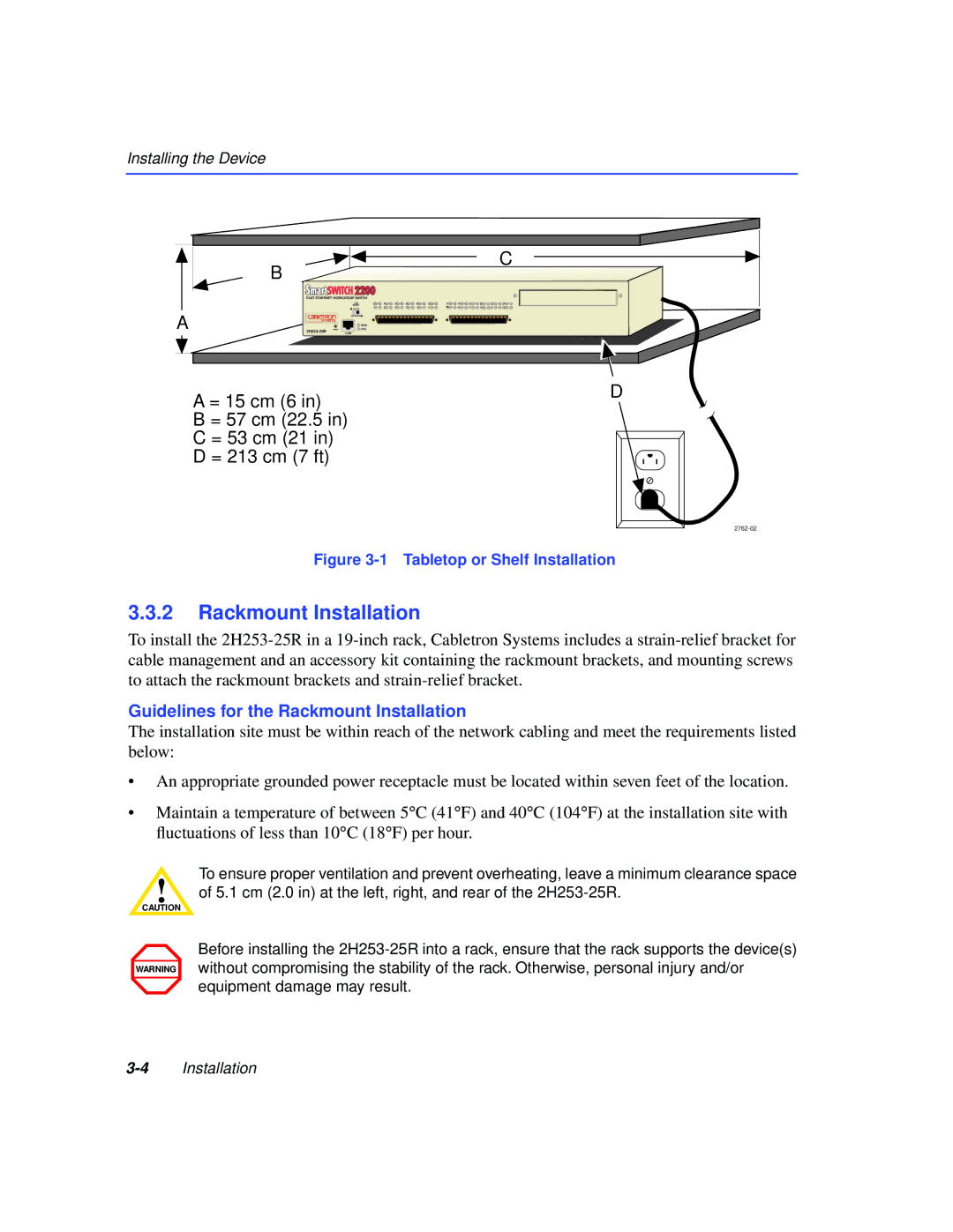
A = 15 cm (6 in)
B = 57 cm (22.5 in) C = 53 cm (21 in) D = 213 cm (7 ft)
2 | 4 | 6 | 8 | 10 | 12 | 14 | 16 | 18 | 20 | 22 | 24 |
1 | 3 | 5 | 7 | 9 | 11 | 13 | 15 | 17 | 19 | 21 | 23 |
D
Figure 3-1 Tabletop or Shelf Installation
3.3.2Rackmount Installation
To install the
Guidelines for the Rackmount Installation
The installation site must be within reach of the network cabling and meet the requirements listed below:
•An appropriate grounded power receptacle must be located within seven feet of the location.
•Maintain a temperature of between 5°C (41°F) and 40°C (104°F) at the installation site with fluctuations of less than 10°C (18°F) per hour.
To ensure proper ventilation and prevent overheating, leave a minimum clearance space
!of 5.1 cm (2.0 in) at the left, right, and rear of the
CAUTION
WARNING
Before installing the