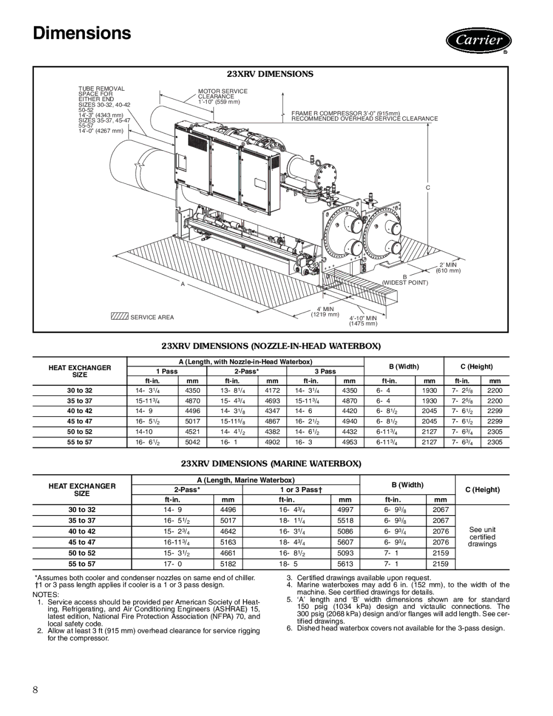
23XRV specifications
The Carrier 23XRV is a high-performance commercial rooftop unit designed for versatility and efficiency in various applications. As part of Carrier's commitment to providing superior HVAC solutions, the 23XRV combines advanced technologies with robust construction to meet the demands of modern commercial environments.One of the standout features of the 23XRV is its superior energy efficiency. The unit is equipped with a variable speed compressor that adjusts the cooling output based on real-time demand. This allows for optimal efficiency even during partial load conditions, significantly reducing energy consumption and operational costs. It boasts a high SEER (Seasonal Energy Efficiency Ratio) and EER (Energy Efficiency Ratio) ratings, making it an environmentally friendly option that helps to lower carbon footprints.
The 23XRV is constructed with a strong focus on durability. Its robust frame and high-quality materials ensure resilience against harsh weather conditions and extend the unit's service life. The design also incorporates sound-attenuating features, minimizing operational noise and making it suitable for noise-sensitive environments like schools and hospitals.
In terms of technology, the Carrier 23XRV utilizes advanced microprocessor controls that enable precise temperature management and system diagnostics. This smart control system provides enhanced functionality, allowing for easy monitoring and configuration through a user-friendly interface. Additionally, the unit is compatible with remote monitoring systems, enabling building managers to track performance and make adjustments as necessary from any location.
The refrigerant used in the 23XRV is R-410A, which is chlorine-free and meets stringent environmental regulations. The choice of refrigerant not only enhances the efficiency of the system but also aligns with global efforts to phase out ozone-depleting substances.
Maintenance and serviceability are also key considerations in the design of the 23XRV. Features such as easy access to components for routine maintenance, modular construction for quicker repairs, and extensive diagnostic capabilities reduce downtime and enhance overall reliability.
Overall, the Carrier 23XRV stands out in the commercial HVAC market with its combination of efficiency, durability, and advanced technology. It is an excellent choice for various commercial applications, providing reliable performance and improved energy management for building owners and operators looking to enhance their HVAC systems.

