UNIT

CENTER OF GRAVITY

UNIT HEIGHT


VICTAULIC CONNECTIONS


X

Y

H (STANDARD)

H (VALUE SOUND)

WATER IN/OUT


30RA035

36.45 [926]

46.08 [1170]

66.5 [1689]

61.0 [1549]


2-1/2"


30RA040

36.24 [921]

44.03 [1118]

66.5 [1689]

61.0 [1549]


2-1/2"


30RA045

36.24 [921]

46.15 [1172]

78.5 [1994]

73.0 [1854]


2-1/2"


AIR FLOW


COIL SIDE


30RA050

36.00 [914]

44.00 [1118]

78.5 [1994]

73.0 [1854]


2-1/2"


42 [1067] MIN.


30RA055

36.48 [927]

44.60 [1133]

78.5 [1994]

73.0 [1854]


2-1/2"


SEE NOTE #4


30RA060

36.50 [927]

44.56 [1132]

78.5 [1994]

73.0 [1854]


2-1/2"


COIL


NOTE: 3 OR 4 FANS


AREA


NOTES:


48 [1219] MIN.


1. DO NOT CAP OR OTHERWISE OBSTRUCT THE


SERVICE


LIQUID LINE TEMPERATURE RELIEF.


CLEARANCE


2. 7/8 [22.4] PILOT HOLE PROVIDED FOR LOCATING FIELD POWER WIRING.


BORDER


ACTUAL HOLE REQUIRED DEPENDS ON FIELD WIRE SIZING.


(NOT TO SCALE)


3. 0.437 [11.10] HOLE USED FOR MOUNTING UNIT.


4. UNIT MUST HAVE CLEARANCES AS FOLLOWS:


PANEL SIDE


CG


TOP - DO NOT RESTRICT.


COIL SIDE - 42 [1067] FROM SOLID SURFACE.


SEE NOTE #4


PANEL SIDE - 48 [1219] PER NEC.


PANEL SIDE


5. SEE TABLE COLUMN H; DIMENSION FOR STANDARD FAN OR VALUE


SEE NOTE #4


SOUND FAN OPTION.


6. CARRIER DOES NOT RECOMMEND INSTALLATION IN A PIT.


7. UNIT CAN BE HANDLED USING THE FORK TRUCK LIFT POCKETS


Y


(MINIMUM OF 60" FORK LENGTH).


48 [1219] MIN.


8. WATER CONNECTIONS RECESSED 4-1/2 INCHES INSIDE UNIT.


COIL


9. DIMENSIONS ARE IN INCHES. DIMENSIONS IN [


AREA


] ARE IN MILLIMETERS


9


X

TOP VIEW

COIL SIDE


42 [1067] MIN.


SEE NOTE #4


88.50 [2247.9]


92.50

[2349.5]


VALUE SOUND FAN OPTION


AIR FLOW


(PICTORIALLY ONLY)


AIR FLOW


RADIUS

20 [508]


CONTROL BOX


HINGED ACCESS


FIELD


CONTROL


CONTROL BOX


WIRING


CONNECTIONS


HINGED ACCESS


H


WATER-IN


SEE NOTE #5


7/8 [22.4]


FIELD POWER ENTRY


SEE NOTE #2


CIRCUIT A


CIRCUIT B


31.74


WATER-OUT


COMPRESSOR


[806.2]


COMPRESSOR


ACCESS


27.98


ACCESS


4.63


[710.7]


[117.6]


11.20


[284.5]


FORK


1.50

RIGHT VIEW

1.50


1.00

[25.4]


[38.1]


a30-4950


[38.1]

1.00

[25.4]


TRUCK


SEE NOTE #3


FRONT VIEW

POCKETS


SEE NOTE #3

44.00


TYP.


TYP.

[1117.6]


REAR VIEW


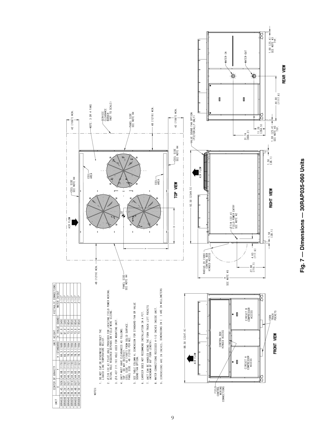
Fig. 7 — Dimensions — 30RAP035-060 Units

Page 9
Image 9
Carrier 30RAP010-060 installation instructions Dimensions 30RAP035-060 Units

30RAP010-060 specifications

The Carrier 30RAP010-060 is a series of rooftop air conditioning units designed for effective climate control in commercial applications. Engineered with advanced technologies, these units are known for their reliability, energy efficiency, and ease of installation, making them a suitable choice for a range of settings including offices, retail spaces, and industrial facilities.

One of the standout features of the 30RAP series is its robust construction. Designed to withstand various environmental conditions, these units come equipped with a weather-resistant cabinet and a corrosion-resistant finish. This durability ensures long-term performance and reduced maintenance costs.

Energy efficiency is a significant characteristic of the Carrier 30RAP series. These units utilize advanced technologies such as a high-efficiency compressor and variable speed fans. The inclusion of economizers also contributes to energy savings by allowing the system to take advantage of outdoor air when the conditions are favorable. With high SEER (Seasonal Energy Efficiency Ratio) ratings, the 30RAP units help businesses reduce operating costs while minimizing their environmental footprint.

The 30RAP series is equipped with smart control systems that provide enhanced operational efficiency and comfort. With features such as programmable thermostats and remote access capabilities, building managers can easily monitor and adjust the system to maintain optimal indoor climate conditions. Additionally, the units are compatible with building automation systems, allowing for seamless integration into a larger HVAC network.

The installation process of the Carrier 30RAP010-060 is streamlined thanks to a compact design and lightweight construction, which simplifies the transportation and placement on rooftops. Moreover, the unit's modular components facilitate easy access for maintenance and repairs, minimizing downtime and improving overall reliability.

In summary, the Carrier 30RAP010-060 series stands out for its combination of durability, energy efficiency, and advanced control technologies. It is an ideal solution for businesses seeking reliable climate control systems that balance performance with cost-effectiveness. Whether for new installations or replacements, these rooftop units provide the necessary flexibility and efficiency needed in today’s commercial environments. With strong backing from Carrier, a leader in HVAC technology, the 30RAP series ensures lasting comfort and operational efficiency.