| | 7 |
| | (HIDDEN) |
6 | | |
| | 3 |
2 | | 4 |
| |
1 | | |
| 5 | a30-4635 |
| |
| | LEGEND |
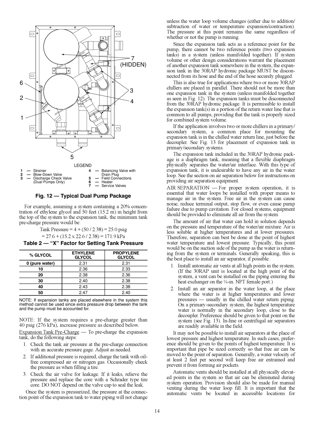
1 | — Strainer | 4 | — Balancing Valve with |
2 | — Blow-Down Valve | | Drain Plug |
3 | — Discharge Check Valve | 5 | — Field Connections |
| (Dual Pumps Only) | 6 | — Heater |
| | 7 | — Service Valves |
Fig. 12 — Typical Dual Pump Package
For example, assuming a system containing a 20% concen- tration of ethylene glycol and 50 feet (15.2 m) in height from the top of the system to the expansion tank, the minimum tank pre-charge pressure would be:
Tank Pressure = 4 + (50 / 2.38) = 25.0 psig = 27.6 + (15.2 x 22.6 / 2.38) = 171.9 kPa
Table 2 — “X” Factor for Setting Tank Pressure
| % GLYCOL | ETHYLENE | PROPYLENE |
| GLYCOL | GLYCOL |
| |
| 0 (pure water) | 2.31 | 2.31 |
| 10 | 2.36 | 2.33 |
| 20 | 2.38 | 2.36 |
| 30 | 2.40 | 2.38 |
| 40 | 2.43 | 2.38 |
| 50 | 2.47 | 2.40 |
NOTE: If expansion tanks are placed elsewhere in the system this method cannot be used since extra pressure drop between the tank and the pump must be accounted for.
NOTE: If the system requires a pre-charge greater than 40 psig (276 kPa), increase pressure as described below.
Expansion Tank Pre-Charge — To pre-charge the expansion tank, do the following steps:
1.Check the tank air pressure at the pre-charge connection with an accurate pressure gage. Adjust as needed.
2.If additional pressure is required, charge the tank with oil- free compressed air or nitrogen gas. Occasionally check the pressure as when filling a tire.
3.Check the air valve for leakage. If it leaks, relieve the pressure and replace the core with a Schrader type tire core. DO NOT depend on the valve cap to seal the leak.
Once the system is pressurized, the pressure at the connec- tion point of the expansion tank to water piping will not change
unless the water loop volume changes (either due to addition/ subtraction of water or temperature expansion/contraction). The pressure at this point remains the same regardless of whether or not the pump is running.
Since the expansion tank acts as a reference point for the pump, there cannot be two reference points (two expansion tanks) in a system (unless manifolded together). If system volume or other design considerations warrant the placement of another expansion tank somewhere in the system, the expan- sion tank in the 30RAP hydronic package MUST be discon- nected from its hose and the end of the hose securely plugged.
This is also true for applications where two or more 30RAP chillers are placed in parallel. There should not be more than one expansion tank in the system (unless manifolded together as seen in Fig. 12). The expansion tanks must be disconnected from the 30RAP hydronic package. It is permissible to install the expansion tank(s) in a portion of the return water line that is common to all pumps, providing that the tank is properly sized for combined system volume.
If the application involves two or more chillers in a primary/ secondary system, a common place for mounting the expansion tank is in the chilled water return line, just before the decoupler. See Fig. 13 for placement of expansion tank in primary/secondary systems.
The expansion tank included in the 30RAP hydronic pack- age is a diaphragm tank, meaning that a flexible diaphragm physically separates the water/air interface. With this type of expansion tank, it is undesirable to have any air in the water loop. See the section on air separation below for instructions on providing air separation equipment.
AIR SEPARATION — For proper system operation, it is essential that water loops be installed with proper means to manage air in the system. Free air in the system can cause noise, reduce terminal output, stop flow, or even cause pump failure due to pump cavitation. For closed systems, equipment should be provided to eliminate all air from the system.
The amount of air that water can hold in solution depends on the pressure and temperature of the water/air mixture. Air is less soluble at higher temperatures and at lower pressures. Therefore, separation can best be done at the point of highest water temperature and lowest pressure. Typically, this point would be on the suction side of the pump as the water is return- ing from the system or terminals. Generally speaking, this is the best place to install an air separator, if possible.
1.Install automatic air vents at all high points in the system. (If the 30RAP unit is located at the high point of the system, a vent can be installed on the piping entering the heat exchanger on the ¼-in. NPT female port.)
2.Install an air separator in the water loop, at the place where the water is at higher temperatures and lower pressures — usually in the chilled water return piping. On a primary-secondary system, the highest temperature water is normally in the secondary loop, close to the decoupler. Preference should be given to that point on the system (see Fig. 13). In-line or centrifugal air separators are readily available in the field.
It may not be possible to install air separators at the place of lowest pressure and highest temperature. In such cases, prefer- ence should be given to the points of highest temperature. It is important that pipe be sized correctly so that free air can be moved to the point of separation. Generally, a water velocity of at least 2 feet per second will keep free air entrained and prevent it from forming air pockets.
Automatic vents should be installed at all physically elevat- ed points in the system so that air can be eliminated during system operation. Provision should also be made for manual venting during the water loop fill. It is important that the automatic vents be located in accessible locations for