Carrier 30RAP010-060 Typical Set Up for Cleaning Process, Cleaning Using a Side Stream Filter

Models: 30RAP010-060

1 40
Download 40 pages 58.51 Kb
Page 16
Image 16
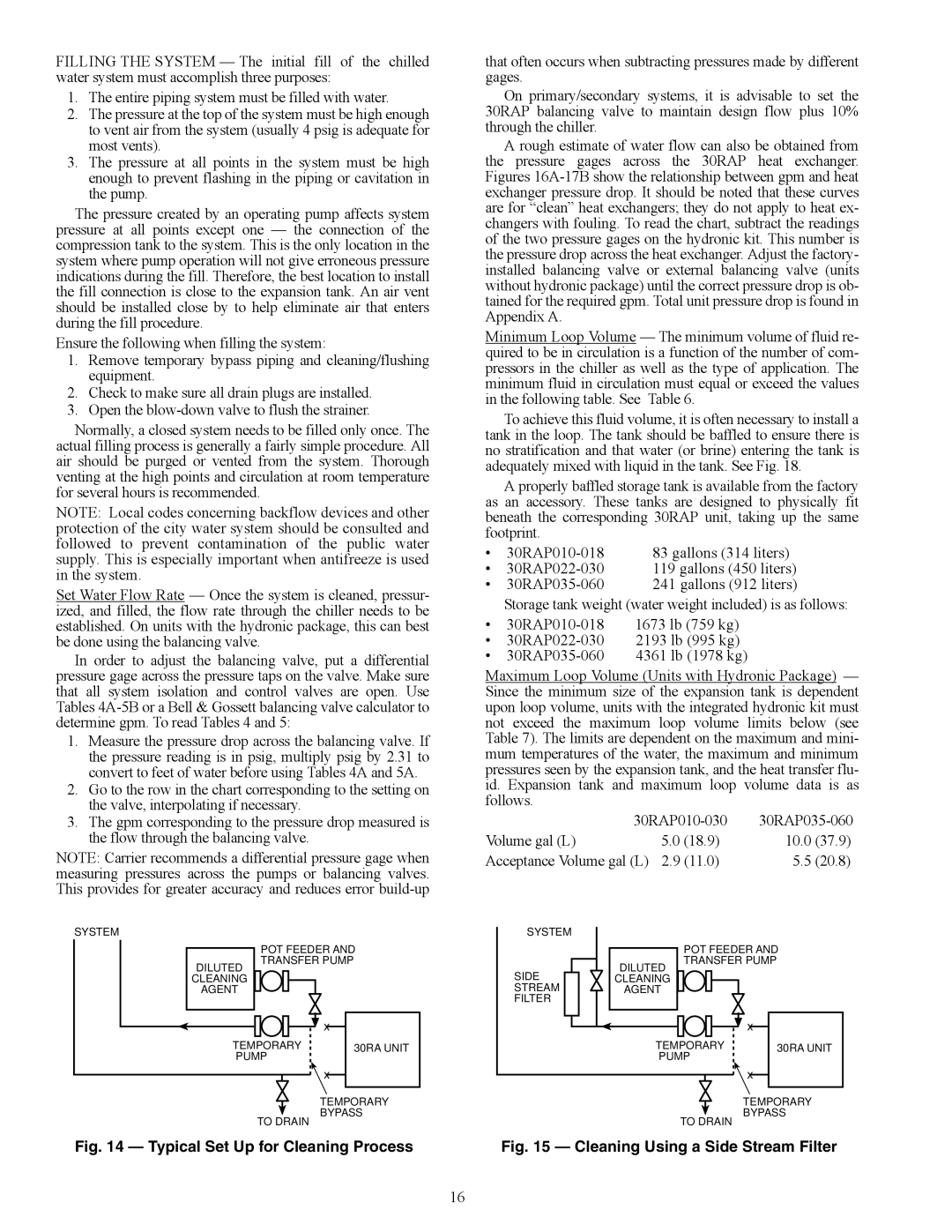
Fig. 14 — Typical Set Up for Cleaning Process

FILLING THE SYSTEM — The initial fill of the chilled water system must accomplish three purposes:

1.The entire piping system must be filled with water.

2.The pressure at the top of the system must be high enough to vent air from the system (usually 4 psig is adequate for most vents).

3.The pressure at all points in the system must be high enough to prevent flashing in the piping or cavitation in the pump.

The pressure created by an operating pump affects system pressure at all points except one — the connection of the compression tank to the system. This is the only location in the system where pump operation will not give erroneous pressure indications during the fill. Therefore, the best location to install the fill connection is close to the expansion tank. An air vent should be installed close by to help eliminate air that enters during the fill procedure.

Ensure the following when filling the system:

1.Remove temporary bypass piping and cleaning/flushing equipment.

2.Check to make sure all drain plugs are installed.

3.Open the blow-down valve to flush the strainer.

Normally, a closed system needs to be filled only once. The actual filling process is generally a fairly simple procedure. All air should be purged or vented from the system. Thorough venting at the high points and circulation at room temperature for several hours is recommended.

NOTE: Local codes concerning backflow devices and other protection of the city water system should be consulted and followed to prevent contamination of the public water supply. This is especially important when antifreeze is used in the system.

Set Water Flow Rate — Once the system is cleaned, pressur- ized, and filled, the flow rate through the chiller needs to be established. On units with the hydronic package, this can best be done using the balancing valve.

In order to adjust the balancing valve, put a differential pressure gage across the pressure taps on the valve. Make sure that all system isolation and control valves are open. Use Tables 4A-5B or a Bell & Gossett balancing valve calculator to determine gpm. To read Tables 4 and 5:

1.Measure the pressure drop across the balancing valve. If the pressure reading is in psig, multiply psig by 2.31 to convert to feet of water before using Tables 4A and 5A.

2.Go to the row in the chart corresponding to the setting on the valve, interpolating if necessary.

3.The gpm corresponding to the pressure drop measured is the flow through the balancing valve.

NOTE: Carrier recommends a differential pressure gage when measuring pressures across the pumps or balancing valves. This provides for greater accuracy and reduces error build-up

that often occurs when subtracting pressures made by different gages.

On primary/secondary systems, it is advisable to set the 30RAP balancing valve to maintain design flow plus 10% through the chiller.

A rough estimate of water flow can also be obtained from the pressure gages across the 30RAP heat exchanger. Figures 16A-17B show the relationship between gpm and heat exchanger pressure drop. It should be noted that these curves are for “clean” heat exchangers; they do not apply to heat ex- changers with fouling. To read the chart, subtract the readings of the two pressure gages on the hydronic kit. This number is the pressure drop across the heat exchanger. Adjust the factory- installed balancing valve or external balancing valve (units without hydronic package) until the correct pressure drop is ob- tained for the required gpm. Total unit pressure drop is found in Appendix A.

Minimum Loop Volume — The minimum volume of fluid re- quired to be in circulation is a function of the number of com- pressors in the chiller as well as the type of application. The minimum fluid in circulation must equal or exceed the values in the following table. See Table 6.

To achieve this fluid volume, it is often necessary to install a tank in the loop. The tank should be baffled to ensure there is no stratification and that water (or brine) entering the tank is adequately mixed with liquid in the tank. See Fig. 18.

A properly baffled storage tank is available from the factory as an accessory. These tanks are designed to physically fit beneath the corresponding 30RAP unit, taking up the same footprint.

30RAP010-018

83 gallons (314 liters)

30RAP022-030

119 gallons (450 liters)

30RAP035-060

241 gallons (912 liters)

Storage tank weight (water weight included) is as follows:

30RAP010-018

1673 lb (759 kg)

30RAP022-030

2193 lb (995 kg)

30RAP035-060

4361 lb (1978 kg)

Maximum Loop Volume (Units with Hydronic Package) — Since the minimum size of the expansion tank is dependent upon loop volume, units with the integrated hydronic kit must not exceed the maximum loop volume limits below (see Table 7). The limits are dependent on the maximum and mini- mum temperatures of the water, the maximum and minimum pressures seen by the expansion tank, and the heat transfer flu- id. Expansion tank and maximum loop volume data is as follows.

30RAP010-030

30RAP035-060

Volume gal (L)

5.0 (18.9)

10.0

(37.9)

Acceptance Volume gal (L)

2.9 (11.0)

5.5

(20.8)

SYSTEM

SYSTEM

DILUTED

POT FEEDER AND TRANSFER PUMP

DILUTED

POT FEEDER AND TRANSFER PUMP

CLEANING

AGENT


x

TEMPORARY

30RA UNIT

PUMP


x

SIDE STREAM FILTER

CLEANING

AGENT


x

TEMPORARY

30RA UNIT

PUMP


x

TEMPORARY

BYPASS

TO DRAIN

Fig. 14 — Typical Set Up for Cleaning Process

TEMPORARY

BYPASS

TO DRAIN

Fig. 15 — Cleaning Using a Side Stream Filter

16

Page 16
Image 16
Carrier 30RAP010-060 installation instructions Typical Set Up for Cleaning Process, Cleaning Using a Side Stream Filter