Step 10 Ð Position Power Exhaust/Barometric Relief Damper Hood Ð All electrical connections have been made and adjusted at the factory. The power exhaust blowers and barometric relief dampers are shipped as- sembled and tilted back into the unit for shipping. Brackets and extra screws are shipped in shrink wrap around the damp- ers. If ordered, each unit will have 4 power exhaust blowers and motors or 4 barometric relief dampers.

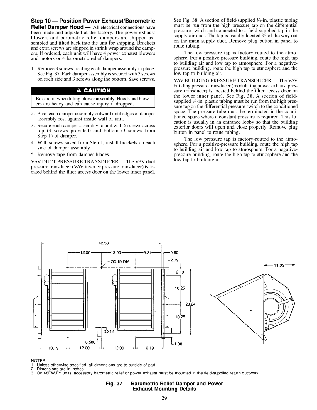
1.Remove 9 screws holding each damper assembly in place. See Fig. 37. Each damper assembly is secured with 3 screws on each side and 3 screws along the bottom. Save screws.

Be careful when tilting blower assembly. Hoods and blow- ers are heavy and can cause injury if dropped.

2.Pivot each damper assembly outward until edges of damper assembly rest against inside wall of unit.

3.Secure each damper assembly to unit with 6 screws across top (3 screws provided) and bottom (3 screws from Step 1) of damper.

4.With screws saved from Step 1, install brackets on each side of damper assembly.

5.Remove tape from damper blades.

VAV DUCT PRESSURE TRANSDUCER Ð The VAV duct pressure transducer (VAV inverter pressure transducer) is lo- cated behind the ®lter access door on the lower inner panel.

See Fig. 38. A section of ®eld-supplied 1¤4-in. plastic tubing must be run from the high pressure tap on the differential pressure switch and connected to a ®eld-supplied tap in the supply-air duct. The tap is usually located 2¤3 of the way out on the main supply duct. Remove plug button in panel to route tubing.

The low pressure tap is factory-routed to the atmo- sphere. For a positive-pressure building, route the high tap to building air and low tap to atmosphere. For a negative- pressure building, route the high tap to atmosphere and the low tap to building air.

VAV BUILDING PRESSURE TRANSDUCER Ð The VAV building pressure transducer (modulating power exhaust pres- sure transducer) is located behind the ®lter access door on the lower inner panel. See Fig. 38. A section of ®eld- supplied 1¤4-in. plastic tubing must be run from the high pres- sure tap on the differential pressure switch to the conditioned space. The pressure tube must be terminated in the condi- tioned space where a constant pressure is required. This lo- cation is usually in an entrance lobby so that the building exterior doors will open and close properly. Remove plug button in panel to route tubing.

The low pressure tap is factory-routed to the atmo- sphere. For a positive-pressure building, route the high tap to building air and low tap to atmosphere. For a negative- pressure building, route the high tap to atmosphere and the low tap to building air.

NOTES:

1.Unless otherwise speci®ed, all dimensions are to outside of part.

2.Dimensions are in inches.

3.On 48EW,EY units, accessory barometric relief or power exhaust must be mounted in the ®eld-supplied return ductwork.

Fig. 37 Ð Barometric Relief Damper and Power

Exhaust Mounting Details

29

Page 29
Image 29
Carrier EW, 48EJ, EK, EY024-048 installation instructions Barometric Relief Damper and Power Exhaust Mounting Details

EW, EY024-048, EK, 48EJ specifications

The Carrier 48EJ, 48AW, 48EK, 48AJ, and 48EY024-068 are cutting-edge rooftop air conditioning units designed for commercial applications. These models are renowned for their reliability, energy efficiency, and innovative technologies aimed at providing optimal indoor comfort.

One of the standout features of these units is their advanced cooling and heating capabilities. They employ a multi-stage compressor system that allows for precise temperature control, accommodating various load requirements. This flexibility is particularly beneficial in commercial settings where the cooling load can fluctuate throughout the day.

Energy efficiency is paramount in today’s environmental landscape, and Carrier has ensured that these models meet stringent efficiency standards. They incorporate high-efficiency scroll compressors, which significantly reduce energy consumption while delivering powerful performance. The units are also equipped with variable speed fans that adjust airflow based on demand, further optimizing energy use.

In terms of construction, these rooftop units feature a robust design that enhances durability and longevity. The cabinet is constructed to withstand harsh weather conditions, ensuring reliable performance year-round. Additionally, the units are equipped with corrosion-resistant coatings, particularly useful in coastal environments where salt exposure can be a concern.

The Carrier 48EJ, 48AW, 48EK, 48AJ, and 48EY models utilize advanced controls and connectivity features, allowing for easy integration into building management systems. This connectivity enables remote monitoring and control, facilitating quick response to changing conditions and simplifying maintenance tasks.

Noise reduction is another key characteristic of these models. They are designed with sound-absorbing insulation and low-noise fan blades to ensure quiet operation, making them suitable for noise-sensitive environments such as schools and hospitals.

These units are also available with various options for air filtration and dehumidification. The use of high-efficiency air filters enhances indoor air quality by trapping dust, pollen, and other airborne particles. Enhanced dehumidification capabilities ensure that spaces remain comfortable even in humid conditions.

In conclusion, the Carrier 48EJ, 48AW, 48EK, 48AJ, and 48EY024-068 rooftop units are engineered to offer exceptional performance, energy efficiency, and durability. With their advanced technologies and user-friendly features, they stand out as reliable solutions for meeting diverse commercial cooling and heating needs, making them a popular choice for many businesses.