To open, loosen the latch bolt using a 7¤16-in. wrench. Pivot the latch so it is not in contact with the door. Open the door. To shut, reverse the above procedure.

NOTE: Disassembly of the top cover may be required under special service circumstances. It is very important that the orientation and position of the top cover be marked on the unit prior to disassembly. This will allow proper replace- ment of the top cover onto the unit and prevent rainwater from leaking into the unit.

IMPORTANT: After servicing is completed, make sure door is closed and relatched properly, and that the latches are tight. Failure to do so can result in water leakage into the evaporator section of the unit.

Cleaning Ð Inspect unit interior at beginning of each heat- ing and cooling season and as operating conditions require. Remove unit side panels and/or open doors for access to unit interior.

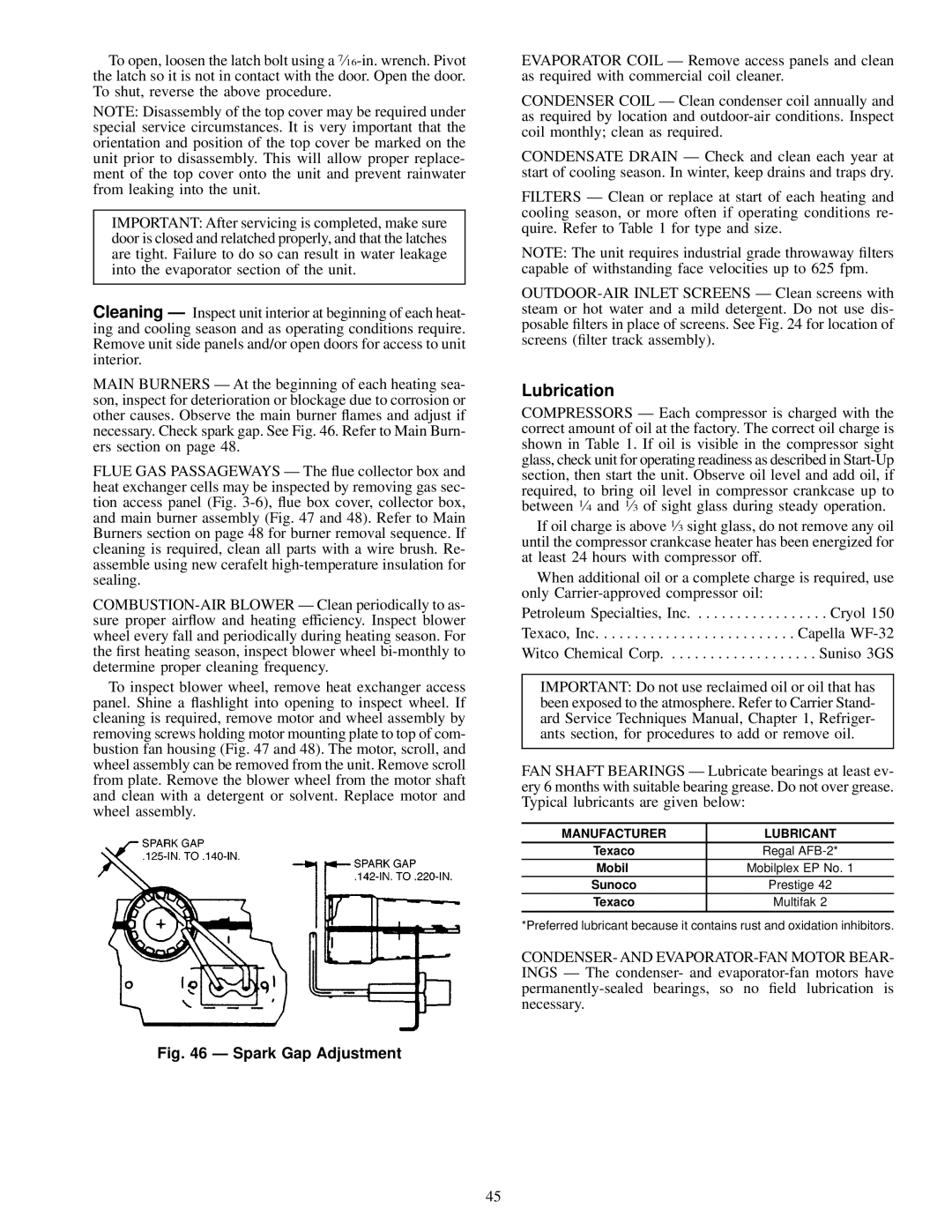
MAIN BURNERS Ð At the beginning of each heating sea- son, inspect for deterioration or blockage due to corrosion or other causes. Observe the main burner ¯ames and adjust if necessary. Check spark gap. See Fig. 46. Refer to Main Burn- ers section on page 48.

FLUE GAS PASSAGEWAYS Ð The ¯ue collector box and heat exchanger cells may be inspected by removing gas sec- tion access panel (Fig. 3-6), ¯ue box cover, collector box, and main burner assembly (Fig. 47 and 48). Refer to Main Burners section on page 48 for burner removal sequence. If cleaning is required, clean all parts with a wire brush. Re- assemble using new cerafelt high-temperature insulation for sealing.

COMBUSTION-AIR BLOWER Ð Clean periodically to as- sure proper air¯ow and heating efficiency. Inspect blower wheel every fall and periodically during heating season. For the ®rst heating season, inspect blower wheel bi-monthly to determine proper cleaning frequency.

To inspect blower wheel, remove heat exchanger access panel. Shine a ¯ashlight into opening to inspect wheel. If cleaning is required, remove motor and wheel assembly by removing screws holding motor mounting plate to top of com- bustion fan housing (Fig. 47 and 48). The motor, scroll, and wheel assembly can be removed from the unit. Remove scroll from plate. Remove the blower wheel from the motor shaft and clean with a detergent or solvent. Replace motor and wheel assembly.

Fig. 46 Ð Spark Gap Adjustment

EVAPORATOR COIL Ð Remove access panels and clean as required with commercial coil cleaner.

CONDENSER COIL Ð Clean condenser coil annually and as required by location and outdoor-air conditions. Inspect coil monthly; clean as required.

CONDENSATE DRAIN Ð Check and clean each year at start of cooling season. In winter, keep drains and traps dry.

FILTERS Ð Clean or replace at start of each heating and cooling season, or more often if operating conditions re- quire. Refer to Table 1 for type and size.

NOTE: The unit requires industrial grade throwaway ®lters capable of withstanding face velocities up to 625 fpm.

OUTDOOR-AIR INLET SCREENS Ð Clean screens with steam or hot water and a mild detergent. Do not use dis- posable ®lters in place of screens. See Fig. 24 for location of screens (®lter track assembly).

Lubrication

COMPRESSORS Ð Each compressor is charged with the correct amount of oil at the factory. The correct oil charge is shown in Table 1. If oil is visible in the compressor sight glass, check unit for operating readiness as described in Start-Up section, then start the unit. Observe oil level and add oil, if required, to bring oil level in compressor crankcase up to between 1¤4 and 1¤3 of sight glass during steady operation.

If oil charge is above 1¤3 sight glass, do not remove any oil until the compressor crankcase heater has been energized for at least 24 hours with compressor off.

When additional oil or a complete charge is required, use only Carrier-approved compressor oil:

Petroleum Specialties, Inc. . . . . . . . . . . . . . . . . . Cryol 150 Texaco, Inc. . . . . . . . . . . . . . . . . . . . . . . . . . Capella WF-32 Witco Chemical Corp. . . . . . . . . . . . . . . . . . . . Suniso 3GS

IMPORTANT: Do not use reclaimed oil or oil that has been exposed to the atmosphere. Refer to Carrier Stand- ard Service Techniques Manual, Chapter 1, Refriger- ants section, for procedures to add or remove oil.

FAN SHAFT BEARINGS Ð Lubricate bearings at least ev- ery 6 months with suitable bearing grease. Do not over grease. Typical lubricants are given below:

MANUFACTURER

LUBRICANT

Texaco

Regal AFB-2*

Mobil

Mobilplex EP No. 1

Sunoco

Prestige 42

Texaco

Multifak 2


*Preferred lubricant because it contains rust and oxidation inhibitors.

CONDENSER- AND EVAPORATOR-FAN MOTOR BEAR- INGS Ð The condenser- and evaporator-fan motors have permanently-sealed bearings, so no ®eld lubrication is necessary.

45

Page 45
Image 45
Carrier EW, 48EJ, EK, EY024-048 installation instructions Lubrication, Manufacturer Lubricant

EW, EY024-048, EK, 48EJ specifications

The Carrier 48EJ, 48AW, 48EK, 48AJ, and 48EY024-068 are cutting-edge rooftop air conditioning units designed for commercial applications. These models are renowned for their reliability, energy efficiency, and innovative technologies aimed at providing optimal indoor comfort.

One of the standout features of these units is their advanced cooling and heating capabilities. They employ a multi-stage compressor system that allows for precise temperature control, accommodating various load requirements. This flexibility is particularly beneficial in commercial settings where the cooling load can fluctuate throughout the day.

Energy efficiency is paramount in today’s environmental landscape, and Carrier has ensured that these models meet stringent efficiency standards. They incorporate high-efficiency scroll compressors, which significantly reduce energy consumption while delivering powerful performance. The units are also equipped with variable speed fans that adjust airflow based on demand, further optimizing energy use.

In terms of construction, these rooftop units feature a robust design that enhances durability and longevity. The cabinet is constructed to withstand harsh weather conditions, ensuring reliable performance year-round. Additionally, the units are equipped with corrosion-resistant coatings, particularly useful in coastal environments where salt exposure can be a concern.

The Carrier 48EJ, 48AW, 48EK, 48AJ, and 48EY models utilize advanced controls and connectivity features, allowing for easy integration into building management systems. This connectivity enables remote monitoring and control, facilitating quick response to changing conditions and simplifying maintenance tasks.

Noise reduction is another key characteristic of these models. They are designed with sound-absorbing insulation and low-noise fan blades to ensure quiet operation, making them suitable for noise-sensitive environments such as schools and hospitals.

These units are also available with various options for air filtration and dehumidification. The use of high-efficiency air filters enhances indoor air quality by trapping dust, pollen, and other airborne particles. Enhanced dehumidification capabilities ensure that spaces remain comfortable even in humid conditions.

In conclusion, the Carrier 48EJ, 48AW, 48EK, 48AJ, and 48EY024-068 rooftop units are engineered to offer exceptional performance, energy efficiency, and durability. With their advanced technologies and user-friendly features, they stand out as reliable solutions for meeting diverse commercial cooling and heating needs, making them a popular choice for many businesses.