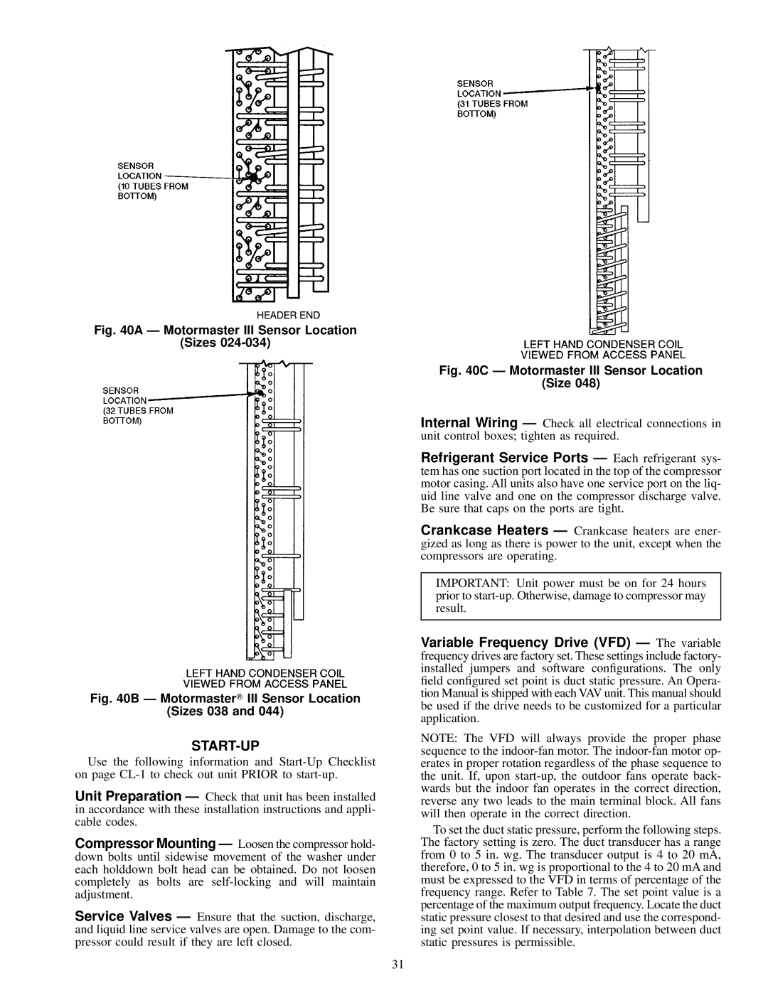
Fig. 40A Ð Motormaster III Sensor Location

(Sizes 024-034)

Fig. 40B Ð Motormaster III Sensor Location

(Sizes 038 and 044)

START-UP

Use the following information and Start-Up Checklist on page CL-1 to check out unit PRIOR to start-up.

Unit Preparation Ð Check that unit has been installed in accordance with these installation instructions and appli- cable codes.

Compressor Mounting Ð Loosen the compressor hold- down bolts until sidewise movement of the washer under each holddown bolt head can be obtained. Do not loosen completely as bolts are self-locking and will maintain adjustment.

Service Valves Ð Ensure that the suction, discharge, and liquid line service valves are open. Damage to the com- pressor could result if they are left closed.

Fig. 40C Ð Motormaster III Sensor Location

(Size 048)

Internal Wiring Ð Check all electrical connections in unit control boxes; tighten as required.

Refrigerant Service Ports Ð Each refrigerant sys- tem has one suction port located in the top of the compressor motor casing. All units also have one service port on the liq- uid line valve and one on the compressor discharge valve. Be sure that caps on the ports are tight.

Crankcase Heaters Ð Crankcase heaters are ener- gized as long as there is power to the unit, except when the compressors are operating.

IMPORTANT: Unit power must be on for 24 hours prior to start-up. Otherwise, damage to compressor may result.

Variable Frequency Drive (VFD) Ð The variable frequency drives are factory set. These settings include factory- installed jumpers and software con®gurations. The only ®eld con®gured set point is duct static pressure. An Opera- tion Manual is shipped with each VAV unit. This manual should be used if the drive needs to be customized for a particular application.

NOTE: The VFD will always provide the proper phase sequence to the indoor-fan motor. The indoor-fan motor op- erates in proper rotation regardless of the phase sequence to the unit. If, upon start-up, the outdoor fans operate back- wards but the indoor fan operates in the correct direction, reverse any two leads to the main terminal block. All fans will then operate in the correct direction.

To set the duct static pressure, perform the following steps. The factory setting is zero. The duct transducer has a range from 0 to 5 in. wg. The transducer output is 4 to 20 mA, therefore, 0 to 5 in. wg is proportional to the 4 to 20 mA and must be expressed to the VFD in terms of percentage of the frequency range. Refer to Table 7. The set point value is a percentage of the maximum output frequency. Locate the duct static pressure closest to that desired and use the correspond- ing set point value. If necessary, interpolation between duct static pressures is permissible.

31

Page 31
Image 31
Carrier EY024-048, 48EJ, EW, EK installation instructions Start-Up

EW, EY024-048, EK, 48EJ specifications

The Carrier 48EJ, 48AW, 48EK, 48AJ, and 48EY024-068 are cutting-edge rooftop air conditioning units designed for commercial applications. These models are renowned for their reliability, energy efficiency, and innovative technologies aimed at providing optimal indoor comfort.

One of the standout features of these units is their advanced cooling and heating capabilities. They employ a multi-stage compressor system that allows for precise temperature control, accommodating various load requirements. This flexibility is particularly beneficial in commercial settings where the cooling load can fluctuate throughout the day.

Energy efficiency is paramount in today’s environmental landscape, and Carrier has ensured that these models meet stringent efficiency standards. They incorporate high-efficiency scroll compressors, which significantly reduce energy consumption while delivering powerful performance. The units are also equipped with variable speed fans that adjust airflow based on demand, further optimizing energy use.

In terms of construction, these rooftop units feature a robust design that enhances durability and longevity. The cabinet is constructed to withstand harsh weather conditions, ensuring reliable performance year-round. Additionally, the units are equipped with corrosion-resistant coatings, particularly useful in coastal environments where salt exposure can be a concern.

The Carrier 48EJ, 48AW, 48EK, 48AJ, and 48EY models utilize advanced controls and connectivity features, allowing for easy integration into building management systems. This connectivity enables remote monitoring and control, facilitating quick response to changing conditions and simplifying maintenance tasks.

Noise reduction is another key characteristic of these models. They are designed with sound-absorbing insulation and low-noise fan blades to ensure quiet operation, making them suitable for noise-sensitive environments such as schools and hospitals.

These units are also available with various options for air filtration and dehumidification. The use of high-efficiency air filters enhances indoor air quality by trapping dust, pollen, and other airborne particles. Enhanced dehumidification capabilities ensure that spaces remain comfortable even in humid conditions.

In conclusion, the Carrier 48EJ, 48AW, 48EK, 48AJ, and 48EY024-068 rooftop units are engineered to offer exceptional performance, energy efficiency, and durability. With their advanced technologies and user-friendly features, they stand out as reliable solutions for meeting diverse commercial cooling and heating needs, making them a popular choice for many businesses.