activation to allow the dampers to open. This delay allows the damper to reach the appropriate position to avoid unnecessary fan overload.

Minimum Position Control

There is a minimum damper position potentiometer on the EconoMi$er IV controller. (See Fig. 42.) The minimum damper position maintains the minimum airflow into the building during the occupied period.

When using demand ventilation, the minimum damper position represents the minimum ventilation position for VOC (volatile organic compound) ventilation requirements. The maximum demand ventilation position is used for fully occupied ventilation.

When demand ventilation control is not being used, the minimum position potentiometer should be used to set the occupied ventilation position. The maximum demand ventilation position should be turned fully clockwise.

Adjust the minimum position potentiometer to allow the minimum amount of outdoor air, as required by local codes, to enter the building. Make minimum position adjustments with at least 10_F temperature difference between the outdoor and return-air temperatures.

To determine the minimum position setting, perform the following procedure:

1.Calculate the appropriate mixed air temperature using the following formula:

Thermostats

The EconoMi$er IV control works with conventional thermostats that have a Y1 (cool stage 1), Y2 (cool stage 2), W1 (heat stage 1), W2 (heat stage 2), and G (fan). The EconoMi$er IV control does not support space temperature sensors. Connections are made at the thermostat terminal connection board located in the main control box.

19


18

LED ON


D


17


16


LED OFF

LED ON


C


15


mA

14


LED OFF


LED ON


B


13


12


LED OFF

LED ON


A


11


10


LED OFF


9


100


40

45

50

55

60

65

70

75

80

85

90

95

DEGREES FAHRENHEIT

C06035

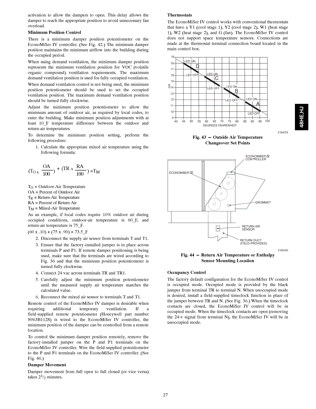
Fig. 43 ---Outside Air Temperature

Changeover Set Points

48HE,HJ

(TO x 100OA ) + (TR x 100RA ) =TM

TO = Outdoor-Air Temperature

OA = Percent of Outdoor Air

TR = Return-Air Temperature

RA = Percent of Return Air

TM = Mixed-Air Temperature

ECONOMI$ER IV

ECONOMI$ER IV CONTROLLER

GROMMET

As an example, if local codes require 10% outdoor air during occupied conditions, outdoor-air temperature is 60_F, and return-air temperature is 75_F.

(60 x .10) + (75 x .90) = 73.5_F

2.Disconnect the supply air sensor from terminals T and T1.

3.Ensure that the factory-installed jumper is in place across terminals P and P1. If remote damper positioning is being used, make sure that the terminals are wired according to Fig. 36 and that the minimum position potentiometer is turned fully clockwise.

4.Connect 24 vac across terminals TR and TR1.

5.Carefully adjust the minimum position potentiometer until the measured supply air temperature matches the calculated value.

6.Reconnect the mixed air sensor to terminals T and T1.

Remote control of the EconoMi$er IV damper is desirable when requiring additional temporary ventilation. If a field-supplied remote potentiometer (Honeywell part number S963B1128) is wired to the EconoMi$er IV controller, the minimum position of the damper can be controlled from a remote location.

To control the minimum damper position remotely, remove the factory-installed jumper on the P and P1 terminals on the EconoMi$er IV controller. Wire the field-supplied potentiometer to the P and P1 terminals on the EconoMi$er IV controller. (See Fig. 46.)

Damper Movement

Damper movement from full open to full closed (or vice versa) takes 21/2 minutes.

RETURN AIR

SENSOR

RETURN DUCT (FIELD-PROVIDED)

C06036

Fig. 44 ---Return Air Temperature or Enthalpy

Sensor Mounting Location

Occupancy Control

The factory default configuration for the EconoMi$er IV control is occupied mode. Occupied mode is provided by the black jumper from terminal TR to terminal N. When unoccupied mode is desired, install a field-supplied timeclock function in place of the jumper between TR and N. (See Fig. 36.) When the timeclock contacts are closed, the EconoMi$er IV control will be in occupied mode. When the timeclock contacts are open (removing the 24-v signal from terminal N), the EconoMi$er IV will be in unoccupied mode.

27

Page 27
Image 27
Carrier 48HJ004---007, 48HE003---006 installation instructions Minimum Position Control, Thermostats, Damper Movement

48HJ004---007, 48HE003---006 specifications

Carrier has long been a trusted name in the HVAC industry, and its models 48HJ004---007 and 48HE003---006 continue that legacy, offering efficient, reliable climate control solutions. These models are designed for different applications, ensuring optimal performance in a variety of environments.

The 48HJ series features advanced rooftop units that are ideal for commercial settings. They come equipped with high-efficiency scroll compressors that provide superior cooling and heating capabilities. This series is noted for its compact design, allowing for easy installation on rooftops or other constrained spaces. The units offer variable capacity operation, which enables them to efficiently meet varying heating and cooling demands without unnecessary energy consumption.

One of the standout features of the 48HJ series is its use of advanced microprocessor controls. This technology allows for precise temperature management and system diagnostics, enhancing the ease of operation while ensuring maximum comfort. Additionally, the series supports advanced connectivity options, enabling integration with building management systems. This allows for remote monitoring and control, making it easier for facility managers to keep track of performance and energy usage.

On the other hand, the 48HE series specializes in high-efficiency heating and cooling performance. These units are designed for larger commercial spaces and come with robust features for enhanced durability and efficiency. Like the 48HJ series, the 48HE models utilize scroll compressors and are equipped with a high-efficiency fan setup for improved airflow and reduced noise levels.

The 48HE also includes an innovative heat pump option, which allows the system to reverse the cooling process to provide heating, making it versatile across different seasonal demands. Both series are designed with eco-friendly refrigerants that comply with the latest environmental regulations, ensuring a minimized ecological footprint.

In terms of energy efficiency, both the 48HJ and 48HE series hold impressive SEER and EER ratings, contributing to reduced operational costs over time. The units are also built with durable, corrosion-resistant materials, ensuring longevity and low maintenance needs.

In conclusion, Carrier 48HJ004---007 and 48HE003---006 models are designed with cutting-edge technology, energy efficiency, and flexibility in mind. Their robust features make them ideal choices for commercial applications, providing reliable comfort and operational excellence. Whether for cooling or heating, these systems stand out in performance and sustainability, earning Carrier's reputation as a leader in the HVAC market.