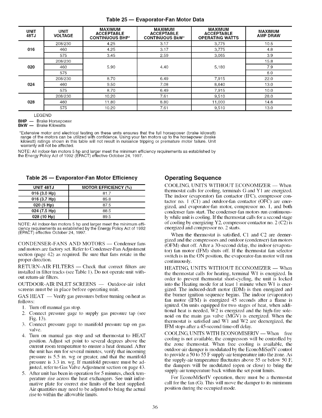
Table 25 --Evaporator-Fan Motor Data

UNIT

UNIT

MAXIMUM

MAXIMUM

MAXIMUM

MAXIMUM

ACCEPTABLE

ACCEPTABLE

ACCEPTABLE

48TJ

VOLTAG E

AMP DRAW

CONTINUOUS BHP*

CONTINUOUS BkW*

OPERATING

WATTS


208/230

4.25

3.17

3,775


10.5

016

460

4.25

3.17

3,775


4.8


575

3.45

2.59

3,065


3.9


208/230


15.8

020

460

5.90

4.40

5,180


7.9


575


6.0


208/230

8.70

6.49

7,915


22.0

024

460

9.50

7.08

8,640


13.0


575

8.70

6.49

7,915


10.0


208/230

10.20

7.61

9,510


28.0

028

460

11.80

8.80

11,000


14.6


575

10.20

7.61

9,510


13.0

LEGEND


BHP -- Brake Horsepower

BkW -- Brake Kilowatts

*Extensive motor and electrical testing on these units ensures that the full horsepower (brake kilowatt) range of the motors can be utilized with confidence. Using your fan motors up to the horsepower (brake kilowatt) ratings shown in this table will not result in nuisance tripping or premature motor failure. Unit warranty will not be affected.

NOTE: All indoor-fan motors 5 hp and larger meet the minimum efficiency requirements as established by the Energy Policy Act of 1992 (EPACT) effective October 24, 1997.

Table 26 --Evaporator-Fan Motor Efficiency

UNIT 48TJMOTOR EFFICIENCY (%)

016

(3.0

Hp)

81.7

016

(3.7

Hp)

65.6

020 (5 Hp)

67.5

024

(7.5

Hp)

66.5

028 (10 Hp)

69.5

NOTE: All indoor-fan motors 5 hp and larger meet the minimum effi- ciency requirements as established by the Energy Policy Act of 1992 (EPACT) effective October 24, 1997.

CONDENSER-FANS AND MOTORS -- Condenser fans and motol.'s am factol T set. Refer to Condenser-Fan Adjustment section (page 42) as required. Be sure that fans rotate in the proper direction.

RETURN-AIR FILTERS- Check that correct filtel.s are

installed in filter tracks (see Table 1). Do not operate unit with- out return-air filters.

OUTDOOR-AIR INLET SCREENS -- Outdoor-air inlet screens must be in place before operating unit.

GAS HEAT -- Verify gas pressmes before turning on heat as follows:

1.Turn off manual gas stop.

2.Connect pressure gage to supply gas pressure tap (see Fig. 13).

3.Connect pressure gage to manifold pressure tap on gas valve.

4.Turn on manual gas stop and set thermostat to HEAT position. Adjust set point to several degrees above the current room temperature to ensure a heat demand. After the unit has mn for sevend minutes, verify that incoming pressure is 5.5 in. wg or greater, and that the manifold

pressure is 3.3 in. wg. If manifold pressure must be ad- justed, refer to Gas Valve Adjustment section on page 43.

5.After unit has been in operation for 5 minutes, check tem- perature rise across the heat exchangers. See unit infor- mative plate for correct rise limits of the heat supplied.

Air quantities may need to be adjusted to bring the actual rise to within the zdlowable limits.

Operating Sequence

COOLING, UNITS WITHOLTT ECONOMIZER -- When thermostat calls for cooling, terminals G and Y I are energized. The indoor (evaporator) fan contactor (IF(?_), compressor con- tactor no. 1 (CI) and outdoor-fan contactor (OFC) are ener- gized, and evaporator-fan motor, compressor no. 1, and both condenser fans stall. The condenser-fan motors mn continuous-

ly while unit is cooling. If the thermostat calls for a second stage of cooling by energizing Y2, compressor contactor no. 2 (C2) is energized and compressor no. 2 starts.

When the thermostat is satisfied, CI and C2 tue deener- gized and the compressors and outdoor (condenser) fan motors

(OFM) shut off. After a 30-second delay, the indoor (evapora- tor) fan motor (IFM) shuts off. If the thermostat fan selector switch is in the ON position, the evaporator-fan motor will run continuously.

HEATING. UNITS WITHOUT ECONOMIZER -- When the thermostat calls for heating, terminal WI is energized. In order to prevent thermostat short-cycling, the unit is locked into the Heating mode for at least 1 minute when WI is ener- gized. The induced-draft motor (IDM) is then energized and the burner ignition sequence begins. The indoor (evaporator) fan motor (IFM) is energized 45 seconds after a fame is ignited. On units equipped for two stages of heat, when addi- tional heat is needed, W2 is enelgized and the high-fire sole-

noid on the main gas valve (MGV) is energized. When the thermostat is satisfied and WI and W2 are deenergized, the IFM stops after a 45-second time-off delay.

COOLING. UNITS WITH ECONOMISERIV -- When free cooling is not available, the compressol_ will be controlled by

the zone thermostat. When free cooling is available, the outdoor-air &unper is modulated by the EconoMiSerIV control to provide a 50 to 55 F supply-air temperature into the zone. As the supply-air temperature fluctuates above 55 or below 50 IF. the &lmpers will be modulated (open or close) to bring the supply-air temperature back within the set point limits.

For EconoMiSerIV operation, there must be a thermostat call for the fan (G). This will move the damper to its minimum position during the occupied mode.

36

Page 36
Image 36
Carrier 48TJ016-028 specifications Evaporator-Fan Motor Data, Evaporator-Fan Motor Efficiency, Operating Sequence

48TJ016-028 specifications

The Carrier 48TJ016-028 is a notable model in the range of packaged rooftop units designed by Carrier, a leader in heating, ventilation, and air conditioning (HVAC) solutions. Tailored specifically for commercial applications, these units provide a blend of efficiency, durability, and reliability, making them suitable for a variety of settings, including offices, retail spaces, and industrial environments.

One of the standout features of the 48TJ series is its energy-efficient performance. Equipped with high-efficiency scroll compressors, these units offer superior cooling capacity while minimizing energy consumption. This aligns with modern sustainability goals, helping businesses reduce their carbon footprint and operational costs. Additionally, the 48TJ units comply with stringent industry standards, such as the ASHRAE 90.1 energy efficiency guidelines, ensuring that users receive a product that meets modern energy performance benchmarks.

The 48TJ016-028 units also include advanced technologies that enhance performance and user comfort. The inclusion of a sophisticated microprocessor control system facilitates precise temperature regulation, allowing for an optimal balance of cooling and heating based on real-time conditions. Moreover, the user-friendly controls make it easy for facility managers to monitor system performance and make adjustments as necessary.

Another notable characteristic of the 48TJ series is its flexible installation options. These rooftop units are designed for easy integration into existing building structures and can be installed on flat or pitched roofs. Their compact design and lightweight construction simplify the installation process while minimizing structural impacts on buildings.

Durability is paramount in the design of the 48TJ units as well. The cabinets are constructed from high-quality materials with corrosion-resistant coatings, ensuring a long lifespan even in harsh environmental conditions. The systems are also equipped with robust insulation to reduce sound levels and improve overall operating efficiency.

Furthermore, the Carrier 48TJ016-028 units offer various options for customization. Users can choose from different airflow configurations, heating options, and accessories, allowing for tailored solutions that meet specific requirements. Whether you are looking for a unit with enhanced filtration, economizer capabilities, or advanced humidity control, the 48TJ series provides the flexibility needed for diverse applications.

In summary, the Carrier 48TJ016-028 units deliver a compelling combination of energy efficiency, advanced technology, and robust construction, making them an ideal choice for commercial HVAC needs. With their versatile features and customizable options, they stand out as reliable solutions for maintaining comfortable indoor environments.