FURNACE

(OR COIL CASING

WHEN USED)

COMBUSTIBLE

FLOORING

DOWNFLOW

SUBBASE

SHEET METAL

PLENUM

FLOOR

OPENING

A96285

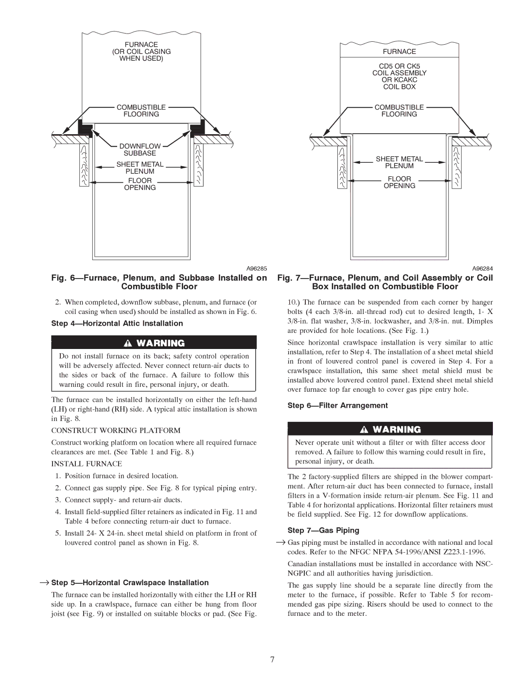
Fig. 6—Furnace, Plenum, and Subbase Installed on

Combustible Floor

2.When completed, downflow subbase, plenum, and furnace (or coil casing when used) should be installed as shown in Fig. 6.

Step 4—Horizontal Attic Installation

Do not install furnace on its back; safety control operation will be adversely affected. Never connect return-air ducts to the sides or back of the furnace. A failure to follow this warning could result in fire, personal injury, or death.

The furnace can be installed horizontally on either the left-hand (LH) or right-hand (RH) side. A typical attic installation is shown in Fig. 8.

CONSTRUCT WORKING PLATFORM

Construct working platform on location where all required furnace clearances are met. (See Table 1 and Fig. 8.)

INSTALL FURNACE

1.Position furnace in desired location.

2.Connect gas supply pipe. See Fig. 8 for typical piping entry.

3.Connect supply- and return-air ducts.

4.Install field-supplied filter retainers as indicated in Fig. 11 and Table 4 before connecting return-air duct to furnace.

5.Install 24- X 24-in. sheet metal shield on platform in front of louvered control panel as shown in Fig. 8.

Step 5—Horizontal Crawlspace Installation

The furnace can be installed horizontally with either the LH or RH side up. In a crawlspace, furnace can either be hung from floor joist (see Fig. 9) or installed on suitable blocks or pad. (See Fig.

FURNACE

CD5 OR CK5

COIL ASSEMBLY

OR KCAKC

COIL BOX

COMBUSTIBLE

FLOORING

SHEET METAL

PLENUM

FLOOR

OPENING

A96284

Fig. 7—Furnace, Plenum, and Coil Assembly or Coil

Box Installed on Combustible Floor

10.) The furnace can be suspended from each corner by hanger bolts (4 each 3/8-in. all-thread rod) cut to desired length, 1- X 3/8-in. flat washer, 3/8-in. lockwasher, and 3/8-in. nut. Dimples are provided for hole locations. (See Fig. 1.)

Since horizontal crawlspace installation is very similar to attic installation, refer to Step 4. The installation of a sheet metal shield in front of louvered control panel is covered in Step 4. For a crawlspace installation, this same sheet metal shield must be installed above louvered control panel. Extend sheet metal shield over furnace top far enough to cover gas pipe entry hole.

Step 6—Filter Arrangement

Never operate unit without a filter or with filter access door removed. A failure to follow this warning could result in fire, personal injury, or death.

The 2 factory-supplied filters are shipped in the blower compart- ment. After return-air duct has been connected to furnace, install filters in a V-formation inside return-air plenum. See Fig. 11 and Table 4 for horizontal applications. Horizontal filter retainers must be field supplied. See Fig. 12 for downflow applications.

Step 7—Gas Piping

Gas piping must be installed in accordance with national and local codes. Refer to the NFGC NFPA 54-1996/ANSI Z223.1-1996.

Canadian installations must be installed in accordance with NSC- NGPIC and all authorities having jurisdiction.

The gas supply line should be a separate line directly from the meter to the furnace, if possible. Refer to Table 5 for recom- mended gas pipe sizing. Risers should be used to connect to the furnace and to the meter.

7

Page 7
Image 7
Carrier 58TMA operating instructions Construct Working Platform, Install Furnace

58TMA specifications

The Carrier 58TMA is a high-efficiency gas furnace designed to provide reliable heating solutions for residential spaces. As part of Carrier's extensive range of heating products, the 58TMA series exemplifies innovation in home comfort technology, offering advanced features that cater to both performance and energy savings.

One of the standout features of the Carrier 58TMA is its variable-speed blower motor. This technology allows for precise airflow control, ensuring consistent temperatures throughout the home while minimizing energy consumption. The variable-speed operation also contributes to quieter operation, enhancing indoor comfort without the disruptive noise commonly associated with traditional furnaces.

The furnace operates with a multi-stage gas valve, enhancing its efficiency. With the ability to modulate heating output based on demand, the 58TMA ensures that the home is heated only as needed. This not only improves energy efficiency but also maintains a more stable and comfortable indoor environment. The combination of the multi-stage gas valve and variable-speed blower results in significant energy cost savings for homeowners.

Another impressive aspect of the Carrier 58TMA is its high Annual Fuel Utilization Efficiency (AFUE) rating. With an AFUE of up to 96%, this gas furnace is engineered to convert a majority of the fuel it consumes into heat, reducing waste and lowering utility bills. Such efficiency ratings make the 58TMA an attractive option for eco-conscious consumers looking to minimize their carbon footprint.

In addition to efficiency and performance, the Carrier 58TMA is designed with durability in mind. The unit features a robust cabinet made from high-quality materials, along with an advanced heat exchanger that ensures long-lasting performance. Moreover, it comes equipped with an advanced electrical ignition system, providing reliable start-up under various conditions without the need for a pilot light.

For added convenience, the 58TMA can be integrated with Carrier's Smart Thermostat technology. This allows homeowners to monitor and adjust their heating settings remotely, facilitating an optimized comfort experience while further enhancing energy savings.

Overall, the Carrier 58TMA's combination of efficiency, advanced technology, and durability makes it a standout option in the market for homeowners seeking dependability and energy savings in their heating solutions. With its innovative features and user-friendly operation, the 58TMA represents a significant advancement in modern furnace design, providing peace of mind and comfort year after year.