13

LS


FRS2


NOTE #8


CONNECTION DIAGRAM


RED


LPS


GRY


HPS


HI


BRN


ORN


YEL


P


RED


RED


LGPS


BRN


GV


DSS


M

C


BLU


GRN


FRS1


#8


HSI

IDM


GRN


FUSED DISCONNECT

(WHEN USED)


ALS1

NOTE


GRN


ILK


SWITCH

(WHEN REQ’D)


JB


NOTE #1


BLK


(WHEN USED)


L1


RED


HEAT


RED

ORN ORNORN

NOTE #6


(WHENUSED)

WHTFSE


GRY

PL6


WHT


L2

WHT

FU2


SET-UP

SWITCH


1

2


SWITCH


BLK

WHT


GRN

GRN


1

2


NORM

ALS2


HI HT *


BLK


LO HT


1

2

3

PL3


ON OFF

ON OFF


YEL


WHT

BLK


BLOWER-


OFF DELAY

SWITCH


(SEC.)

3

4


WHT

BLK


RED


90 SEC


PL2


135 SEC


YEL


BLK


180 SEC *


2-STAGE


2 1

8 7


WHT


225 SEC


FURNACE


ON OFF

ON OFF


CONTROL


3

9


BLK


FACTORY SETTINGS


BRN


GRY

PR1

PR2


WHT


L1

L2


CAP

WHT

BLK


ORN


COMMON


*


NOTE #4


BRN

BRN


RED


HI-COOL


BLOWER-OFF DELAY


COM


WHT


TRAN


23 4

RED


BLU

GRN


BLOWER-OFF DELAY


HI-GAS

EAC-2


HI


BLK


LOW-HEAT ONLY


1

HIGH-HEAT ONLY


P1

HEAT


MED HI


YEL


LO-GAS


MED


ON OFF


EAC-1


NOTE #15


ORN


TWIN


1


11 10

HEAT


MED LO


BLU


RED

BLU


TEST


TJ2


SPARE SPARE


LO


BLWM


M


RED


3


12

SEC1


RED


W2 Com W/W1

Y/Y2 R

G HUM

LED

S


SEC2

FU1


LEGEND


24V


BLU


TO 115VAC FIELD DISCONNECT SWITCH

SCHEMATIC DIAGRAM (NATURAL GAS & PROPANE)

ILK


EQUIPMENT GROUND

NOTE #1


BHI / LOR

LO-GAS-HEAT


L2


LO


MED LO


BLWM


BHT / CLR


HI-GAS-HEAT


L1


NOTE #15


BLWR


SPARE

MED


HI COM


HI-COOL

SPARE

MED HI


NOTE #4

BRN

BRN


COMMON


HSIR

EAC-1

EAC-2


CAP


PL2

3

PL6

1

HSI


2


IHI / LOR


9


LO


IDR


4

PL3

2

HI


1


7


3

COM

IDM


PR1


PR2


8


115VAC


FU1

SEC1

TRAN

SEC2


1


24VAC


HPSR

N/A


NOTE #5


5


6

N/A


2


12 N/A


FRS2


HUM


MGVR-2


2

FRS1


LS


3 (WHEN USED)


R


9


ALS2

ALS1

TWIN


TWINNING


6


TEST


SLAVE


JUMPER


PL1


DSS


TJ


W/W1

MASTER


NOTE #8 LPS


5

(WHEN USED)


LGPS


ALS1

AUXILIARY LIMIT SWITCH, OVERTEMP. MANUAL RESET, SPST (N.C.)

ALS2

AUXILIARY LIMIT SWITCH, OVERTEMP. AUTO RESET, SPST (N.C.)

BHI / LOR

BLOWER MOTOR SPEED CHANGE RELAY, SPDT

BHT / CLR

BLOWER MOTOR SPEED CHANGE RELAY, SPDT

BLWM

BLOWER MOTOR, 4 or 5 -SPEED, PERMANENT-SPLIT-CAPACITOR

BLWR

BLOWER MOTOR RELAY, SPST (N.O.)

CAP

CAPACITOR

CPU

MICROPROCESSOR AND CIRCUITRY

DSS

DRAFT SAFEGUARD SWITCH (N.C.)

EAC-1

ELECTRONIC AIR CLEANER CONNECTION (115 VAC, 1 AMP MAX.)

EAC-2

ELECTRONIC AIR CLEANER CONNECTION (COMMON)

FRS1

FLAME ROLLOUT SWITCH OVERTEMP. MANUAL RESET, SPST (N.C.)

FRS2

FLAME ROLLOUT SWITCH OVERTEMP. MANUAL RESET, SPST (N.C.)

FSE

FLAME-PROVING SENSOR ELECTRODE

FU1

FUSE, 3 AMP, AUTOMOTIVE BLADE TYPE, FACTORY INSTALLED

FU2

FUSE, FIELD INSTALLED

GV

GAS VALVE, REDUNDANT LOW-HEAT OPERATORS, 2-STAGE

HPS

HIGH-HEAT PRESSURE SWITCH, SPST (N.O.)

HPSR

HIGH-HEAT PRESSURE SWITCH RELAY, SPST (N.C.)

HSI

HOT-SURFACE IGNITER (115 VAC)

HSIR

HOT-SURFACE IGNITOR RELAY, SPST (N.O.)

HUM

24VAC HUMIDIFIER CONNECTION (0.5 AMP. MAX.)

IDM

INDUCED DRAFT MOTOR, 2-SPEED, SHADED-POLE

IDR

INDUCER MOTOR RELAY, SPST (N.O.)

IHI / LOR

INDUCER MOTOR SPEED CHANGE RELAY, SPDT

ILK

BLOWER DOOR INTERLOCK SWITCH, SPST (N.O.)

JB

JUNCTION BOX

LED

LIGHT-EMITTING DIODE FOR STATUS CODES

LGPS

LOW GAS-PRESSURE SWITCH, SPST (N.O.)

LPS

LOW-HEAT PRESSURE SWITCH, SPST (N.O.)

LS

LIMIT SWITCH, OVERTEMPERATURE-AUTO RESET, SPST (N.C.)

MGVR

MAIN GAS VALVE RELAY, DPST (N.O.)


-1 = VALVE

-2 = HUMIDIFIER

PL1

12-CIRCUIT CONNECTOR

PL2

9-CIRCUIT CONNECTOR

PL3

3-CIRCUIT IDM CONNECTOR

PL6

2-CIRCUIT HSI CONNECTOR

SW1

HIGH-HEAT-ONLY SWITCH, SPST (MANUAL)*

SW2

LOW-HAT-ONLY SWITCH, SPST (MANUAL)*

SW3 & 4

BLOWER-OFF DELAY SETTING SWITCHES,


SPST (MANUAL)*


TJ

TWINNING JUMPER, SPDT FOR MASTER OR


SLAVE STATUS (MANUAL CHANGE OVER)

TRAN

TRANSFORMER-115VAC/24VAC

TWIN/TEST

1-CIRCUIT TWINNING BUSS CONNECTOR,

ALSO STATUS CODE RECALL

JUNCTION

TERMINAL

CONTROL TERMINAL

FACTORY POWER WIRING (115VAC)

FACTORY CONTROL WIRING (24VAC)

FIELD POWER WIRING (115VAC)

FIELD CONTROL WIRING (24VAC)

CONDUCTOR ON CONTROL

FIELD WIRING SCREW TERMINAL

FIELD GROUND

EQUIPMENT GROUND

FIELD SPLICE

PLUG RECEPTACLE


SW1


NOTE #8


W2

CPU


4


HPS


MGVR-1


1

M

P

HI


Y/Y2


10

C

GV


G


NOTE#7


7

N/A

FSE


8


COM


11 N/A


NOTES:

SW4 SW3 SW2

9.

Symbols are an electrical representation only.

1.

Use only copper wire between the disconnect switch and the unit.

2.

If any of the original wire, as supplied, must be replaced, use the

10.

BLOWER-ON DELAY: Gas heating 45 seconds,


same or equivalent type wire.


Cooling/Heat Pump 2 seconds.

3.

Inducer (IDM) and blower (BLWM) motors contain internal auto-reset

11.

Cooling/Heat Pump BLOWER-OFF DELAY is 90


thermal overload switches.


seconds.


4.

Blower motor speed selections are for average conditions. See


12.

IGNITION-LOCKOUT will occur after four consecutive


Installation Instructions for details on optimum speed selection.


unsuccessful trials-for-ignition. Control will automatically

5.

Replace only with a 3-AMP fuse.


reset after three hours.

6.

Auxiliary limit switches (ALS1 & 2) used on some horizontal and

13.

7.

some downflow models.


Control must be grounded at pin 10 of 12-pin connector.

This wire must be connected to furnace sheet metal for

14.

NA - Not Applicable


control to prove flame.


15.

Spare terminal and wire not available on some

8.

Factory connected when LGPS not used.


applications. Insulate connector if not available.

COMPONENT TEST

To initiate the component test sequence with no thermostat inputs and with all inducer Post-Purge and Blower-Off Delay periods completed, short the "TWIN/TEST" terminal to the "COM" terminal for about two seconds. The control will

turn ON the inducer motor Low-Speed, inducer motor High-Speed, HSI, blower motor Low-Gas-Heat Speed, blower motor High-Gas-Heat Speed, and blower motor High-Cool Speed for 7-15 seconds each. Neither the gas valve nor the humidifier will be

turned ON.

324459-101 REV. A

A97508

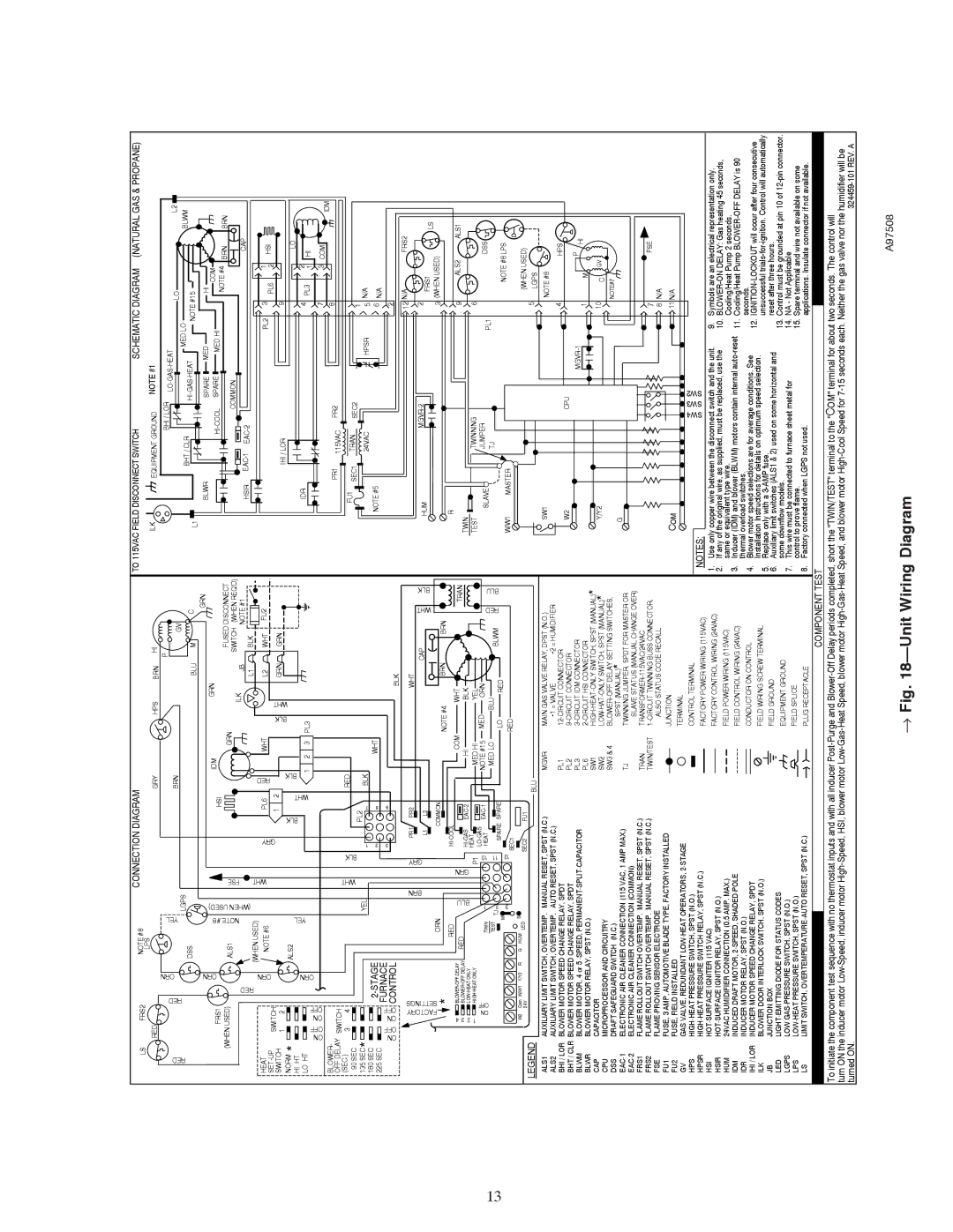
Fig. 18—Unit Wiring Diagram

Page 13
Image 13
Carrier 58TMA operating instructions → -Unit Wiring Diagram, Connection Diagram

58TMA specifications

The Carrier 58TMA is a high-efficiency gas furnace designed to provide reliable heating solutions for residential spaces. As part of Carrier's extensive range of heating products, the 58TMA series exemplifies innovation in home comfort technology, offering advanced features that cater to both performance and energy savings.

One of the standout features of the Carrier 58TMA is its variable-speed blower motor. This technology allows for precise airflow control, ensuring consistent temperatures throughout the home while minimizing energy consumption. The variable-speed operation also contributes to quieter operation, enhancing indoor comfort without the disruptive noise commonly associated with traditional furnaces.

The furnace operates with a multi-stage gas valve, enhancing its efficiency. With the ability to modulate heating output based on demand, the 58TMA ensures that the home is heated only as needed. This not only improves energy efficiency but also maintains a more stable and comfortable indoor environment. The combination of the multi-stage gas valve and variable-speed blower results in significant energy cost savings for homeowners.

Another impressive aspect of the Carrier 58TMA is its high Annual Fuel Utilization Efficiency (AFUE) rating. With an AFUE of up to 96%, this gas furnace is engineered to convert a majority of the fuel it consumes into heat, reducing waste and lowering utility bills. Such efficiency ratings make the 58TMA an attractive option for eco-conscious consumers looking to minimize their carbon footprint.

In addition to efficiency and performance, the Carrier 58TMA is designed with durability in mind. The unit features a robust cabinet made from high-quality materials, along with an advanced heat exchanger that ensures long-lasting performance. Moreover, it comes equipped with an advanced electrical ignition system, providing reliable start-up under various conditions without the need for a pilot light.

For added convenience, the 58TMA can be integrated with Carrier's Smart Thermostat technology. This allows homeowners to monitor and adjust their heating settings remotely, facilitating an optimized comfort experience while further enhancing energy savings.

Overall, the Carrier 58TMA's combination of efficiency, advanced technology, and durability makes it a standout option in the market for homeowners seeking dependability and energy savings in their heating solutions. With its innovative features and user-friendly operation, the 58TMA represents a significant advancement in modern furnace design, providing peace of mind and comfort year after year.