58TMA specifications
The Carrier 58TMA is a high-efficiency gas furnace designed to provide reliable heating solutions for residential spaces. As part of Carrier's extensive range of heating products, the 58TMA series exemplifies innovation in home comfort technology, offering advanced features that cater to both performance and energy savings.One of the standout features of the Carrier 58TMA is its variable-speed blower motor. This technology allows for precise airflow control, ensuring consistent temperatures throughout the home while minimizing energy consumption. The variable-speed operation also contributes to quieter operation, enhancing indoor comfort without the disruptive noise commonly associated with traditional furnaces.
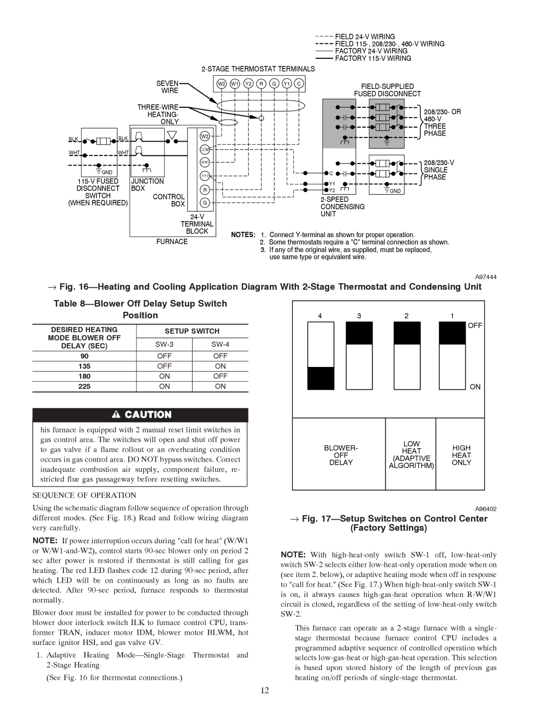
The furnace operates with a multi-stage gas valve, enhancing its efficiency. With the ability to modulate heating output based on demand, the 58TMA ensures that the home is heated only as needed. This not only improves energy efficiency but also maintains a more stable and comfortable indoor environment. The combination of the multi-stage gas valve and variable-speed blower results in significant energy cost savings for homeowners.
Another impressive aspect of the Carrier 58TMA is its high Annual Fuel Utilization Efficiency (AFUE) rating. With an AFUE of up to 96%, this gas furnace is engineered to convert a majority of the fuel it consumes into heat, reducing waste and lowering utility bills. Such efficiency ratings make the 58TMA an attractive option for eco-conscious consumers looking to minimize their carbon footprint.
In addition to efficiency and performance, the Carrier 58TMA is designed with durability in mind. The unit features a robust cabinet made from high-quality materials, along with an advanced heat exchanger that ensures long-lasting performance. Moreover, it comes equipped with an advanced electrical ignition system, providing reliable start-up under various conditions without the need for a pilot light.
For added convenience, the 58TMA can be integrated with Carrier's Smart Thermostat technology. This allows homeowners to monitor and adjust their heating settings remotely, facilitating an optimized comfort experience while further enhancing energy savings.
Overall, the Carrier 58TMA's combination of efficiency, advanced technology, and durability makes it a standout option in the market for homeowners seeking dependability and energy savings in their heating solutions. With its innovative features and user-friendly operation, the 58TMA represents a significant advancement in modern furnace design, providing peace of mind and comfort year after year.

