Carrier | CXM Controls |
|
|
Diagnostic Features
The LED on the CXM board advises the technician of the current status of the CXM control. The LED can display either the current CXM mode or the last fault in memory if in test mode. If there is no fault in memory, the LED will flash Code 1 (when in test mode).
CXM Control Start-up Operation
The control will not operate until all inputs and safety controls are checked for normal conditions. The compressor will have a 5 minute
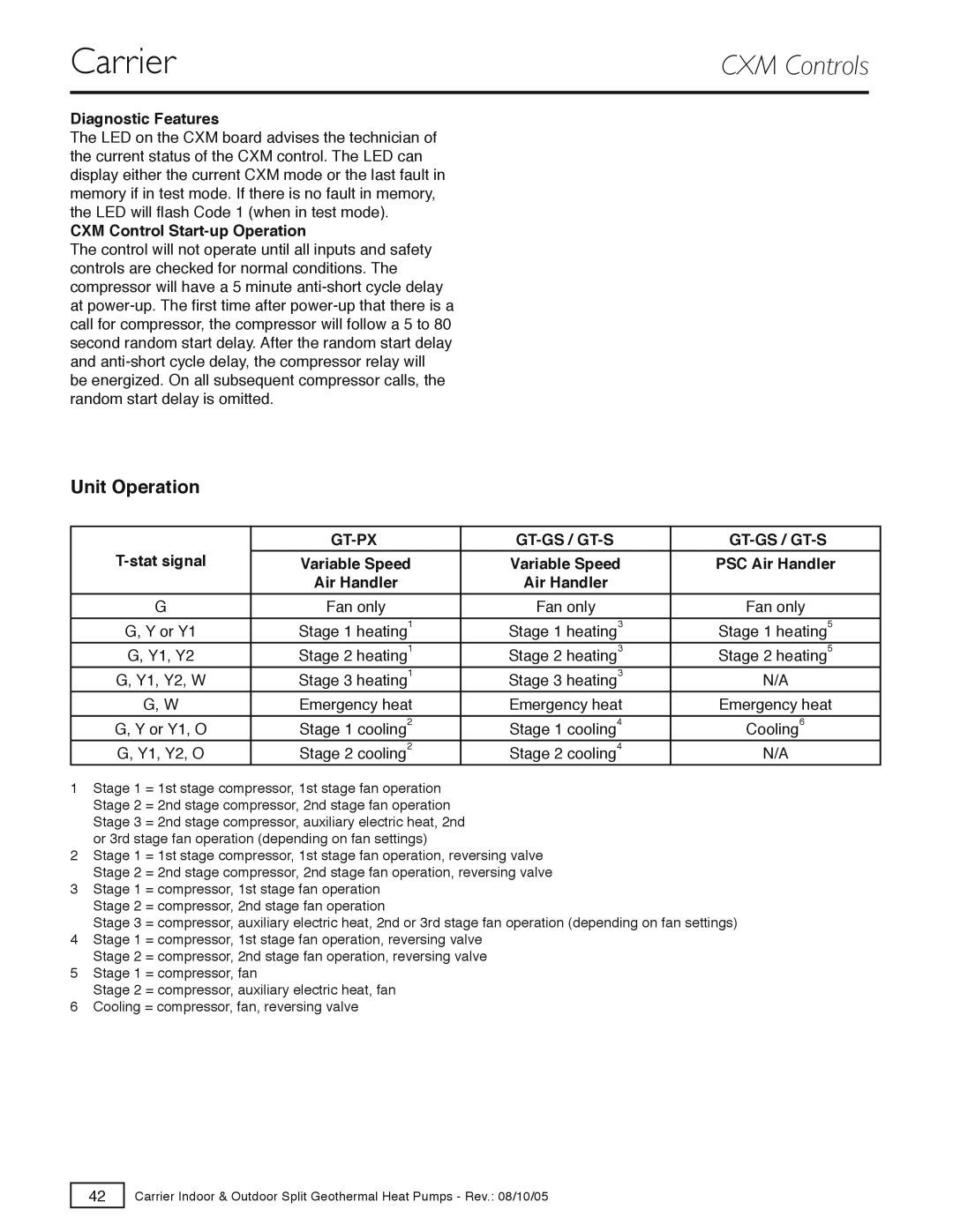
Unit Operation
|
|
|
|
|
|
|
|
|
|
|
|
|
|
|
|
|
|
| |
|
|
|
|
|
|
|
|
|
|
| Variable Speed |
| Variable Speed |
| PSC Air Handler | ||||
|
| Air Handler |
| Air Handler |
|
|
| ||
G |
| Fan only |
| Fan only |
| Fan only | |||
G, Y or Y1 |
| Stage 1 heating1 |
| Stage 1 heating3 |
| Stage 1 heating5 | |||
G, Y1, Y2 |
| Stage 2 heating1 |
| Stage 2 heating3 |
| Stage 2 heating5 | |||
G, Y1, Y2, W |
| Stage 3 heating1 |
| Stage 3 heating3 |
| N/A | |||
G, W |
| Emergency heat |
| Emergency heat |
| Emergency heat | |||
|
|
|
|
|
|
|
|
|
|
G, Y or Y1, O |
| Stage 1 cooling2 |
| Stage 1 cooling4 |
| Cooling6 | |||
G, Y1, Y2, O |
| Stage 2 cooling2 |
| Stage 2 cooling4 |
| N/A | |||
1Stage 1 = 1st stage compressor, 1st stage fan operation Stage 2 = 2nd stage compressor, 2nd stage fan operation Stage 3 = 2nd stage compressor, auxiliary electric heat, 2nd or 3rd stage fan operation (depending on fan settings)
2Stage 1 = 1st stage compressor, 1st stage fan operation, reversing valve Stage 2 = 2nd stage compressor, 2nd stage fan operation, reversing valve
3Stage 1 = compressor, 1st stage fan operation Stage 2 = compressor, 2nd stage fan operation
Stage 3 = compressor, auxiliary electric heat, 2nd or 3rd stage fan operation (depending on fan settings)
4Stage 1 = compressor, 1st stage fan operation, reversing valve Stage 2 = compressor, 2nd stage fan operation, reversing valve
5Stage 1 = compressor, fan
Stage 2 = compressor, auxiliary electric heat, fan
6Cooling = compressor, fan, reversing valve
42
Carrier Indoor & Outdoor Split Geothermal Heat Pumps - Rev.: 08/10/05
