Installing the control unit
1. Strength evaluation table |
2. Units for body weight |
3. Pitch sound setting
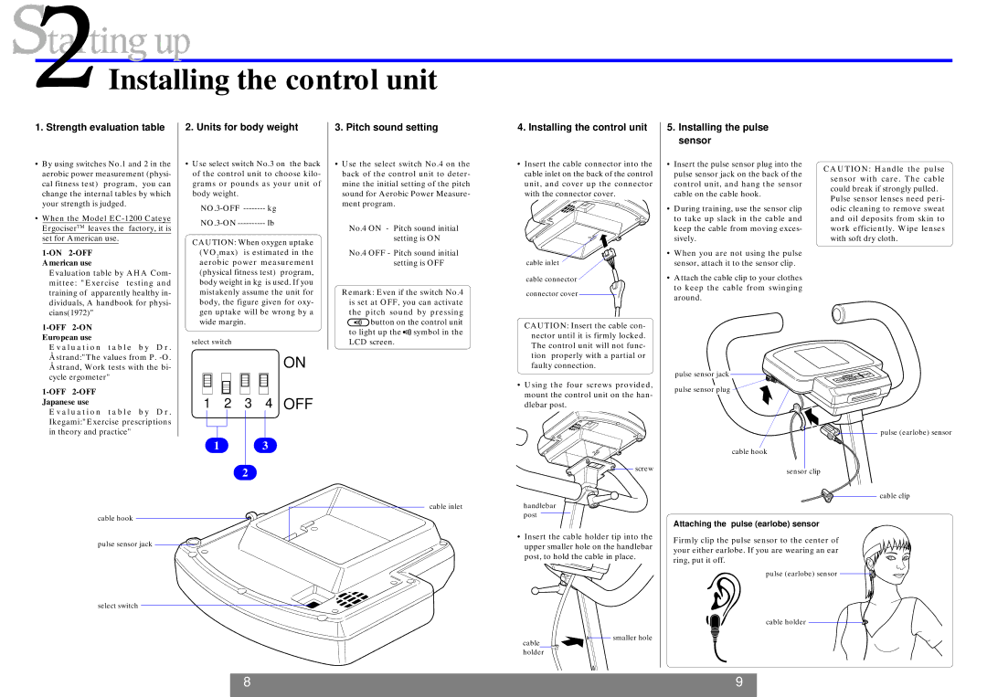
4. Installing the control unit |
5.Installing the pulse sensor
• By using switches No.1 and 2 in the | ||||
| aerobic power measurement (physi- | |||
| cal fitness test) program, you can | |||
| change the internal tables by which | |||
| your strength is judged. |
| ||
• When the Model | ||||
| ErgociserTM leaves the | factory, it is | ||
|
| set for American use. |
| |
|
|
|
| |
| American use |
| ||
|
| Evaluation table by AHA Com- | ||
|
| mittee: "Exercise | testing and | |
|
| training of apparently healthy in- | ||
|
| dividuals, A handbook for physi- | ||
|
| cians(1972)" |
| |
|
|
| ||
| European use |
| ||
• Use select switch No.3 on the back |
of the control unit to choose kilo- |
grams or pounds as your unit of |
body weight. |
CAUTION: When oxygen uptake (VO2max) is estimated in the aerobic power measurement (physical fitness test) program, body weight in kg is used. If you mistakenly assume the unit for body, the figure given for oxy- gen uptake will be wrong by a wide margin.
•Use the select switch No.4 on the back of the control unit to deter- mine the initial setting of the pitch sound for Aerobic Power Measure- ment program.
No.4 ON - Pitch sound initial setting is ON
No.4 OFF - Pitch sound initial setting is OFF
Remark: Even if the switch No.4 is set at OFF, you can activate the pitch sound by pressing the![]() button on the control unit to light up the
button on the control unit to light up the![]()
![]() symbol in the
symbol in the
• Insert the cable connector into the |
cable inlet on the back of the control |
unit, and cover up the connector |
with the connector cover. |
cable inlet
cable connector
connector cover
CAUTION: Insert the cable con- nector until it is firmly locked.
•Insert the pulse sensor plug into the pulse sensor jack on the back of the control unit, and hang the sensor cable on the cable hook.
•During training, use the sensor clip to take up slack in the cable and keep the cable from moving exces- sively.
•When you are not using the pulse sensor, attach it to the sensor clip.
•Attach the cable clip to your clothes to keep the cable from swinging around.
CAUTION: Handle the pulse sensor with care. The cable could break if strongly pulled.
Pulse sensor lenses need peri- odic cleaning to remove sweat and oil deposits from skin to work efficiently. Wipe lenses with soft dry cloth.
E v a l u a t i o n t a b l e b y D r . Åstrand:"The values from P.
1-OFF 2-OFF Japanese use
E v a l u a t i o n t a b l e b y D r . Ikegami:"Exercise prescriptions in theory and practice"
select switch
ON
1 2 3 4 OFF
13
2
LCD screen.
The control unit will not func- tion properly with a partial or faulty connection.
•Using the four screws provided, mount the control unit on the han- dlebar post.
screw
pulse sensor jack![]()
![]()
![]()
pulse sensor plug
![]() pulse (earlobe) sensor
pulse (earlobe) sensor
cable hook
sensor clip
cable clip
cable inlet
cable hook
pulse sensor jack ![]()
select switch
handlebar post
•Insert the cable holder tip into the upper smaller hole on the handlebar post, to hold the cable in place.
![]()
![]() smaller hole
smaller hole
cable
holder
Attaching the pulse (earlobe) sensor
Firmly clip the pulse sensor to the center of your either earlobe. If you are wearing an ear ring, put it off.
pulse (earlobe) sensor ![]()
![]()
cable holder
8 | 9 |