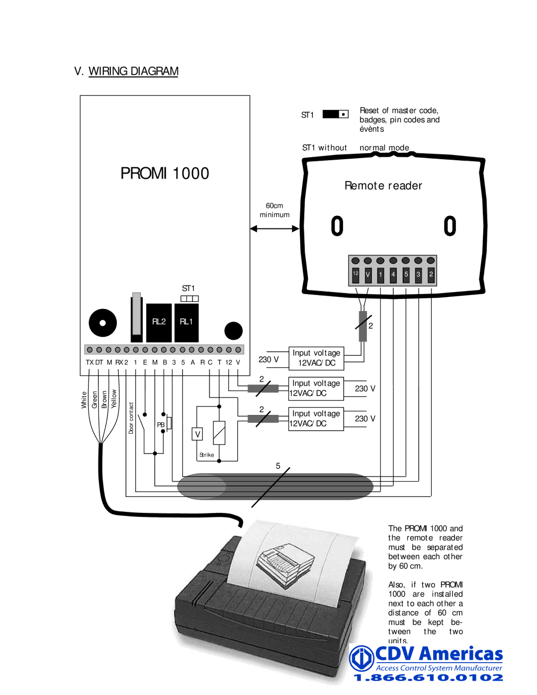
V. WIRING DIAGRAM
PROMI 1000
|
| ST1 |
|
| RL2 RL1 |
TX DT M RX 2 1 E M B 3 5 A R C T 12 V | ||
White Green Brown Yellow | contact | PB |
| Door | |
| V | |
|
| |
|
| Strike |
ST1 |
|
|
| Reset of master code, | |||
|
|
| |||||
|
|
| badges, pin codes and | ||||
|
|
|
| ||||
|
|
|
| évènts | |||
ST1 without normal mode | |||||||
|
|
|
|
|
|
|
|
Remote reader
60cm
minimum
12![]()
![]() V
V ![]()
![]() 1
1 ![]()
![]() 4
4 ![]()
![]() 5
5![]()
![]() 3
3 ![]()
![]() 2
2
2
|
|
|
|
|
|
|
|
|
|
|
|
| Input voltage |
|
|
|
|
230 V |
|
|
|
| ||||
|
|
|
| |||||
12VAC/DC |
|
|
|
| ||||
|
|
|
|
|
|
|
| |
2 |
|
|
|
|
|
|
|
|
|
|
|
|
|
|
|
| |
|
| Input voltage | 230 V | |||||
|
|
|
| 12VAC/DC | ||||
|
|
|
| |||||
2 |
|
|
|
|
|
|
| |
|
|
|
|
|
|
|
| |
|
|
|
|
|
|
|
| |
|
|
| Input voltage | 230 V | ||||
|
|
|
| |||||
|
|
|
| 12VAC/DC | ||||
5 |
|
|
|
|
| |||
|
|
|
|
|
| |||
|
|
|
|
|
| |||
The PROMI 1000 and the remote reader must be separated between each other by 60 cm.
Also, if two PROMI 1000 are installed next to each other a distance of 60 cm must be kept be- tween the two units.