Connecting to 10BASE-T and 100BASE-TX Devices
When connecting the ports to 10BASE-T and 100BASE-TX devices, such as servers, workstations, and routers, you can use a two or four twisted-pair, straight-through cable wired for 10BASE-T and100BASE-TX. Figure B-6shows the two twisted-pair, straight-through cable schematics. Figure B-8shows the four twisted-pair, straight-through cable schematics.
When connecting the ports to 10BASE-T- and 100BASE-TX devices, such as switches or repeaters, you can use a two or four twisted-pair, crossover cable. Figure B-7shows the two twisted-pair, crossover cable schematics. Figure B-9shows the four twisted-pair, crossover cable schematics.
You can use Category 3, 4, or 5 cabling when connecting to 10BASE-T devices. You must use Category 5 cabling when connecting to 100BASE-TX devices.
Connecting to 1000BASE-T Devices
When connecting the ports to 1000BASE-T devices, such as servers, workstations, and routers, you must use a four twisted-pair, Category 5, straight-through cable wired for 10BASE-T, 100BASE-TX, and 1000BASE-T. Figure B-10shows the straight-through cable schematics.
When connecting the ports to other devices, such as switches or repeaters, you must use a four twisted-pair, Category 5, crossover cable. Figure B-11shows the crossover cable schematics.
Note Be sure to use a four twisted-pair, Category 5 cable when connecting to a 1000BASE-T device.
Note Use a straight-through cable to connect two ports only when one port is designated with an X. Use a crossover cable to connect two ports when both ports are designated with an X or when both ports do not have an X.
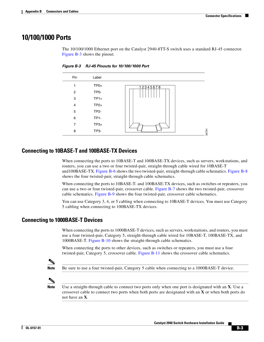
Catalyst 2940 Switch Hardware Installation Guide