3HP c-Class BladeSystem Architecture
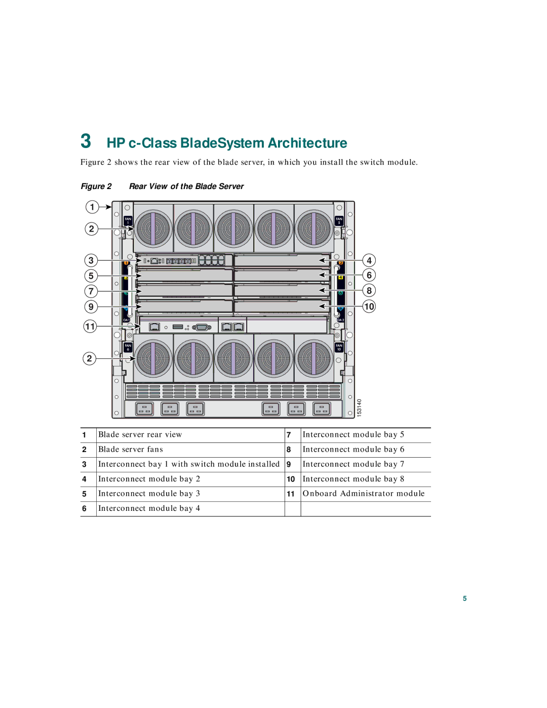
Figure 2 shows the rear view of the blade server, in which you install the switch module.
Figure 2 Rear View of the Blade Server
1 |
2 |
3 |
5 |
7 |
9 |
11 |
2 |
4
6
8
10
![]()
![]() 153140
153140
1 | Blade server rear view | 7 | Interconnect module bay 5 |
|
|
|
|
2 | Blade server fans | 8 | Interconnect module bay 6 |
|
|
|
|
3 | Interconnect bay 1 with switch module installed | 9 | Interconnect module bay 7 |
|
|
|
|
4 | Interconnect module bay 2 | 10 | Interconnect module bay 8 |
|
|
|
|
5 | Interconnect module bay 3 | 11 | Onboard Administrator module |
|
|
|
|
6 | Interconnect module bay 4 |
|
|
|
|
|
|
5