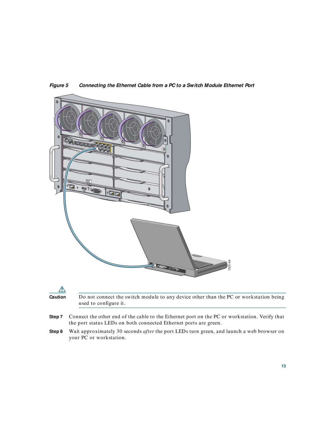
Figure 5 Connecting the Ethernet Cable from a PC to a Switch Module Ethernet Port
SYST |
| |
STAT |
| |
DLX |
| |
SPD |
| |
MODE | CONSOLE | |
| ||
UID | 17 |
| 20 |
MEDIA |
|
DETECT | PORTS |
| |
17 |
|
18 |
|
19 | |
| 20 |
| 17x |
|
17x 21x |
| |
20x | 24x | 23x |
| ||
| 18x |
|
|
| 24x |


 153144
Caution Do not connect the switch module to any device other than the PC or workstation being used to configure it.
Step 7 Connect the other end of the cable to the Ethernet port on the PC or workstation. Verify that the port status LEDs on both connected Ethernet ports are green.
Step 8 Wait approximately 30 seconds after the port LEDs turn green, and launch a web browser on your PC or workstation.
13