Step 4 Ensure that the release latch on the switch module is in the open position (perpendicular to the module):
SYST |
|
|
| |
STAT |
|
|
| |
DLX |
|
|
| |
SPD |
|
|
| |
WS- |
| MODE | CONSOLE | |
CBS- |
| |||
|
| 3020- |
| |
|
|
| HPQ | |
UID | 17 |
| |
| 20 |
MEDIA |
|
DETECT |
|
PORTS | |
| |
17 |
|
18 |
|
19 | |
| 20 |
17x | 17x | |
21x | ||
| ||
20x | 24x | |
| ||
| 18x |
23x
24x
 153141
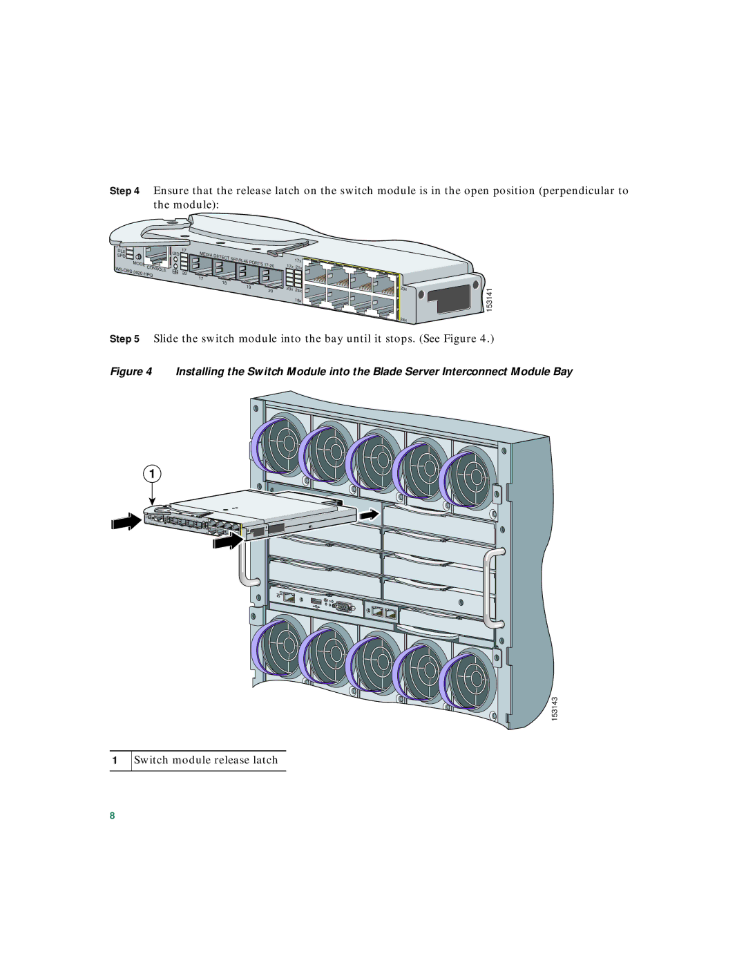
Step 5 Slide the switch module into the bay until it stops. (See Figure 4.)
Figure 4 Installing the Switch Module into the Blade Server Interconnect Module Bay
1
SYST |
|
|
STAT |
|
|
DLX |
|
|
SPD |
|
|
MODE | CONSOLE | |
| ||
| ||
UID | 17 |
| 20 |
MEDIA |
|
DETECT | PORTS |
| |
17 |
|
18 |
|
19 | |
| 20 |
17x |
|
17x 21x |
|
20x 24x | 23x |
18x |
|
| 24x |
153143
1
Switch module release latch
8