Chapter 2 Installing the Cisco Unified Videoconferencing 3545 Gateway
Requirements for Installation
Table
Component | Description |
|
|
ALARM LEDs | Displays alarm events for the PRI line. |
| • YELLOW |
| remote side. |
| • |
| gateway. |
|
|
PRI LINE connectors | |
| gateway ISDN PRI port. |
|
|
Cisco Unified Videoconferencing 3545 Serial Gateway RTM
The Rear Transition Module (RTM) provides the serial line connections for the Cisco Unified
Videoconferencing 3545 Serial Gateway.
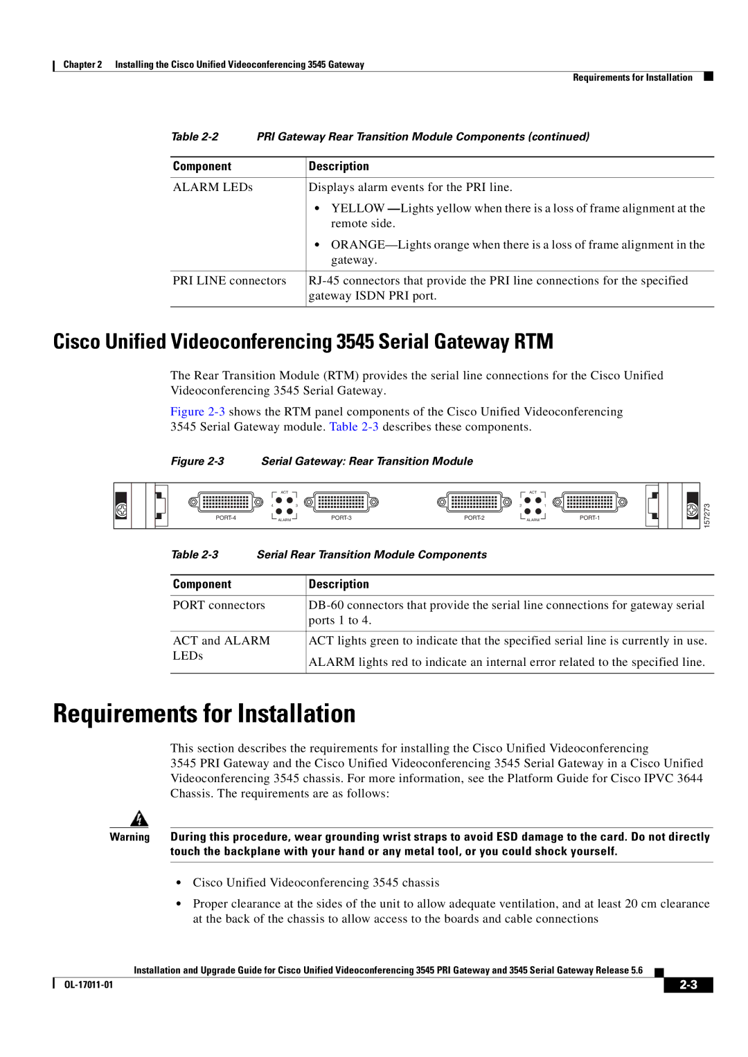
Figure 2-3 shows the RTM panel components of the Cisco Unified Videoconferencing 3545 Serial Gateway module. Table 2-3 describes these components.
Figure 2-3 Serial Gateway: Rear Transition Module
| ACT |
|
| ACT |
|
4 |
| 3 | 2 |
| 1 |
ALARM | ALARM |
157273
Table | Serial Rear Transition Module Components | |
|
|
|
Component |
| Description |
|
| |
PORT connectors | ||
|
| ports 1 to 4. |
|
| |
ACT and ALARM | ACT lights green to indicate that the specified serial line is currently in use. | |
LEDs |
| ALARM lights red to indicate an internal error related to the specified line. |
|
| |
|
|
|
Requirements for Installation
This section describes the requirements for installing the Cisco Unified Videoconferencing
3545 PRI Gateway and the Cisco Unified Videoconferencing 3545 Serial Gateway in a Cisco Unified Videoconferencing 3545 chassis. For more information, see the Platform Guide for Cisco IPVC 3644 Chassis. The requirements are as follows:
Warning During this procedure, wear grounding wrist straps to avoid ESD damage to the card. Do not directly touch the backplane with your hand or any metal tool, or you could shock yourself.
•Cisco Unified Videoconferencing 3545 chassis
•Proper clearance at the sides of the unit to allow adequate ventilation, and at least 20 cm clearance at the back of the chassis to allow access to the boards and cable connections
Installation and Upgrade Guide for Cisco Unified Videoconferencing 3545 PRI Gateway and 3545 Serial Gateway Release 5.6
|
| ||
|
|