Chapter 2 Installing the Cisco Unified Videoconferencing 3545 Gateway
How to Perform the Initial Gateway Configuration
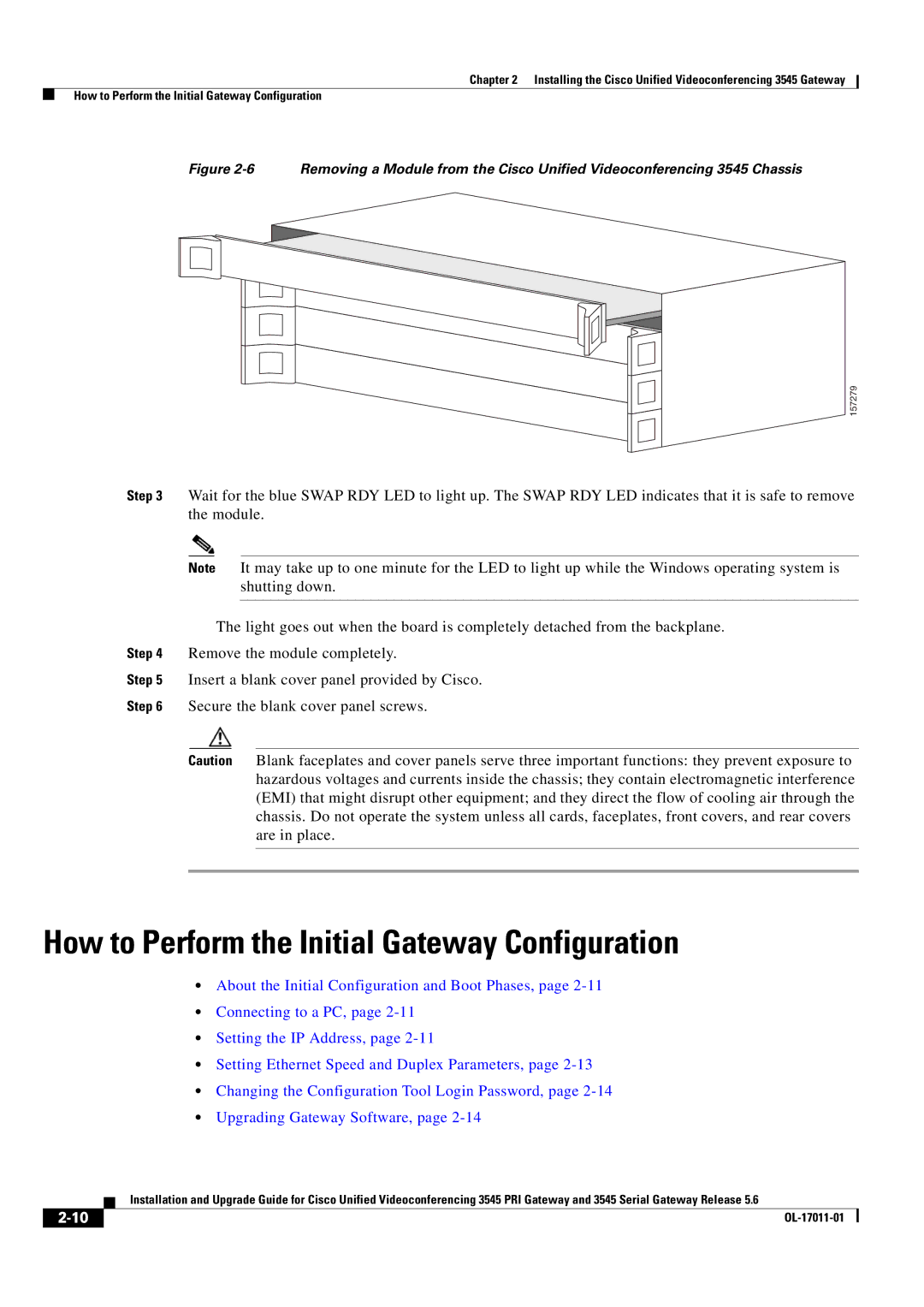
Figure 2-6 Removing a Module from the Cisco Unified Videoconferencing 3545 Chassis
157279
Step 3 Wait for the blue SWAP RDY LED to light up. The SWAP RDY LED indicates that it is safe to remove the module.
Note It may take up to one minute for the LED to light up while the Windows operating system is shutting down.
The light goes out when the board is completely detached from the backplane.
Step 4 Remove the module completely.
Step 5 Insert a blank cover panel provided by Cisco.
Step 6 Secure the blank cover panel screws.
Caution Blank faceplates and cover panels serve three important functions: they prevent exposure to hazardous voltages and currents inside the chassis; they contain electromagnetic interference (EMI) that might disrupt other equipment; and they direct the flow of cooling air through the chassis. Do not operate the system unless all cards, faceplates, front covers, and rear covers are in place.
How to Perform the Initial Gateway Configuration
•About the Initial Configuration and Boot Phases, page
•Connecting to a PC, page
•Setting the IP Address, page
•Setting Ethernet Speed and Duplex Parameters, page
•Changing the Configuration Tool Login Password, page
•Upgrading Gateway Software, page
| Installation and Upgrade Guide for Cisco Unified Videoconferencing 3545 PRI Gateway and 3545 Serial Gateway Release 5.6 |