Connecting Power to the Fan Tray
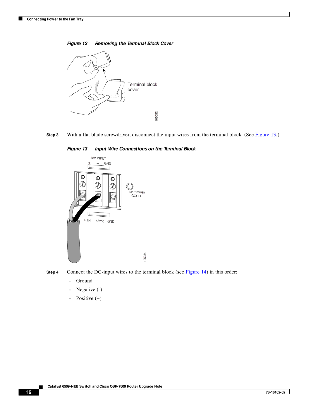
Figure 12 Removing the Terminal Block Cover
Terminal block cover
105082
Step 3 With a flat blade screwdriver, disconnect the input wires from the terminal block. (See Figure 13.)
Figure 13 Input Wire Connections on the Terminal Block
48V INPUT 1
+
GND
INPUT POWER
GOOD
RTN |
105084
Step 4 Connect the
•Ground
•Negative
•Positive (+)
Catalyst
16 |
| |
|
