Connecting Power to the Fan Tray
Connecting Site Power to the Fan Tray for DC-Input Systems
Note To provide redundancy, you may choose to connect each fan terminal block to a separate power source.
Note Each input of the fan tray is rated 10 A @
Warning This product requires
Warning Before performing any of the following procedures, ensure that power is removed from the DC circuit. Statement 1003
To connect the high speed fan tray to an external DC power source, follow these steps:
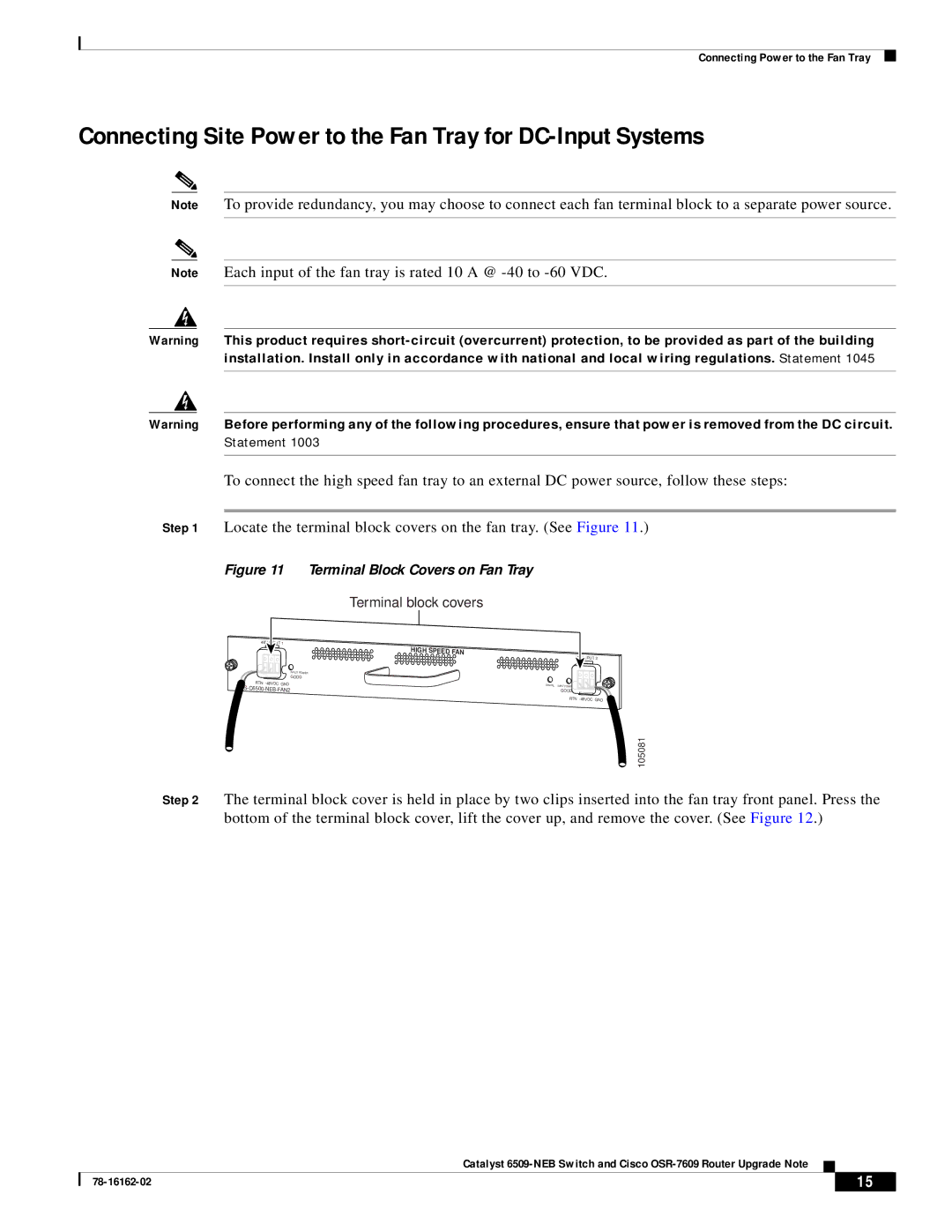
Step 1 Locate the terminal block covers on the fan tray. (See Figure 11.)
Figure 11 Terminal Block Covers on Fan Tray
Terminal block covers
48V INPUT 1
INPUT POWER
GOOD
RTN
HIGH SPEED FAN ![]()
![]()
![]()
![]()
![]()
![]()
![]()
![]()
![]()
![]()
![]()
![]()
![]()
![]()
![]()
![]()
![]()
![]()
![]() 48V INPUT 2
48V INPUT 2
FAN FAIL INPUT POWER
GOOD
RTN
105081
Step 2 The terminal block cover is held in place by two clips inserted into the fan tray front panel. Press the bottom of the terminal block cover, lift the cover up, and remove the cover. (See Figure 12.)
Catalyst
| 15 |
| |
|
|