Connect the Support Bar to the Cisco Unified IP Phone
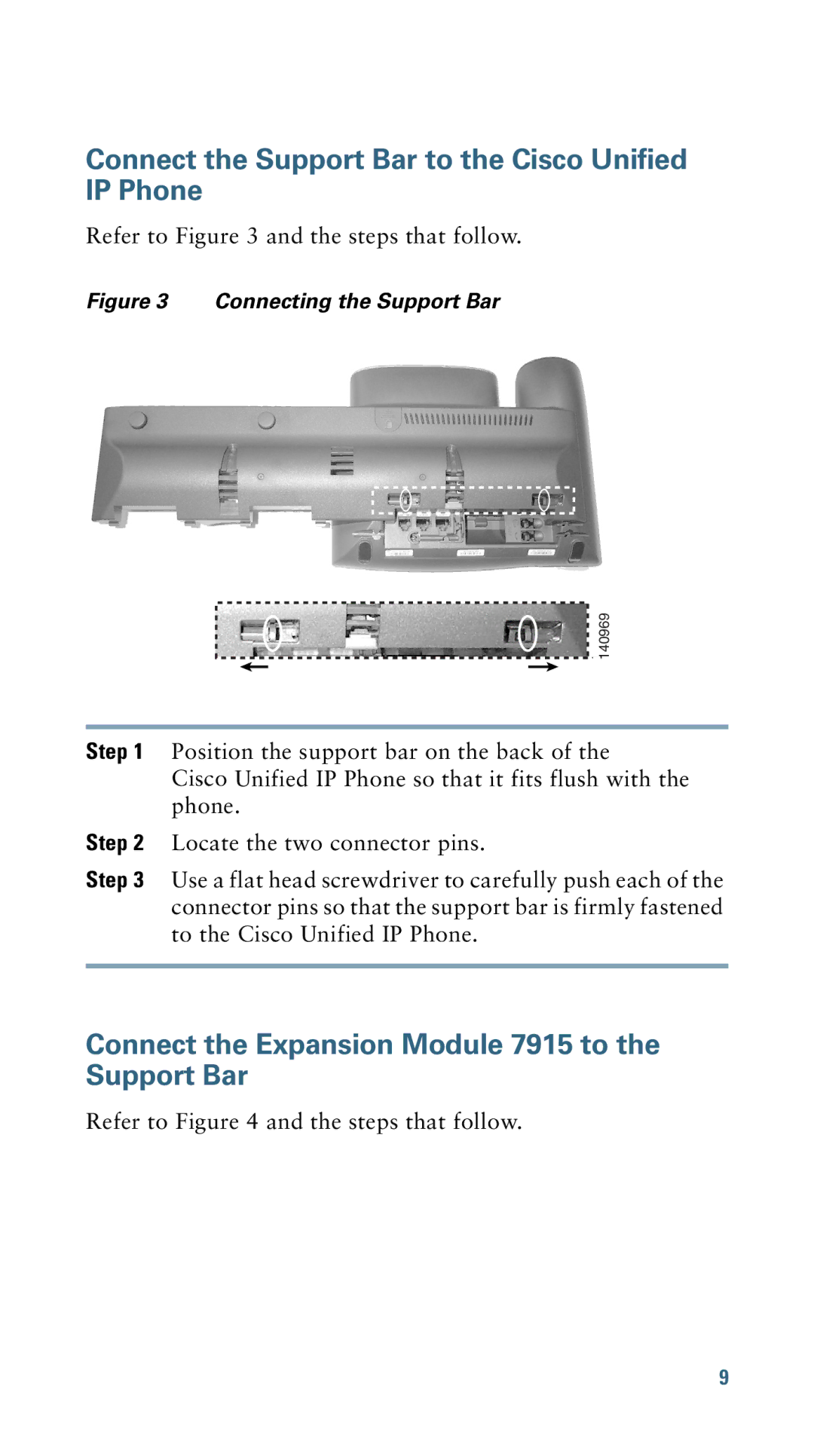
Refer to Figure 3 and the steps that follow.
Figure 3 Connecting the Support Bar
| 140969 | ||||
|
|
|
|
|
|
|
| ||||
Step 1 | Position the support bar on the back of the | ||||
| Cisco Unified IP Phone so that it fits flush with the | ||||
| phone. | ||||
Step 2 | Locate the two connector pins. | ||||
Step 3 | Use a flat head screwdriver to carefully push each of the | ||||
| connector pins so that the support bar is firmly fastened | ||||
| to the Cisco Unified IP Phone. | ||||
|
|
|
|
|
|
Connect the Expansion Module 7915 to the Support Bar
Refer to Figure 4 and the steps that follow.
9
