Generac Portable Products Power Transfer System
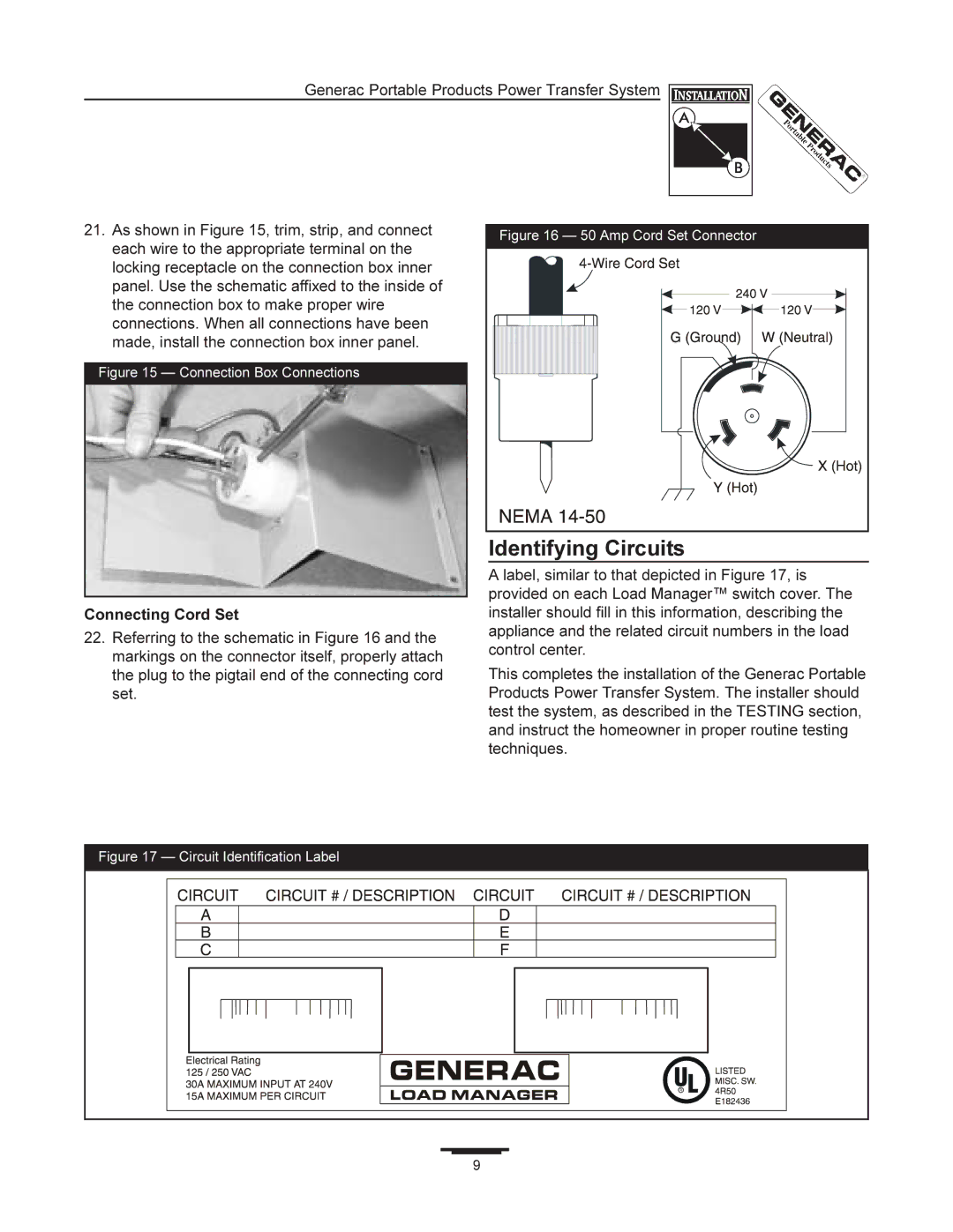
21. As shown in Figure 15, trim, strip, and connect | Figure 16 — 50 Amp Cord Set Connector | |
each wire to the appropriate terminal on the | ||
| ||
locking receptacle on the connection box inner |
| |
panel. Use the schematic affixed to the inside of |
| |
the connection box to make proper wire |
| |
connections. When all connections have been |
| |
made, install the connection box inner panel. |
| |
Figure 15 — Connection Box Connections |
|
Connecting Cord Set
22.Referring to the schematic in Figure 16 and the markings on the connector itself, properly attach the plug to the pigtail end of the connecting cord set.
Identifying Circuits
A label, similar to that depicted in Figure 17, is provided on each Load Manager™ switch cover. The installer should fill in this information, describing the appliance and the related circuit numbers in the load control center.
This completes the installation of the Generac Portable Products Power Transfer System. The installer should test the system, as described in the TESTING section, and instruct the homeowner in proper routine testing techniques.
Figure 17 — Circuit Identification Label
9 |