Manuals
/
Generac
/
Lawn and Garden
/
Spreader
Generac
1403-0
manual
Load Manager Schematic Diagram
Models:
1403-0
1
11
16
16
Download
16 pages
50.19 Kb
8
9
10
11
12
13
14
15
Troubleshooting
Install
Parts list
Load Manager Schematic Diagram
Wire Detached From Breaker
Warranty
Operating Procedure
Testing
Load Manager Switch
Page 11
Image 11
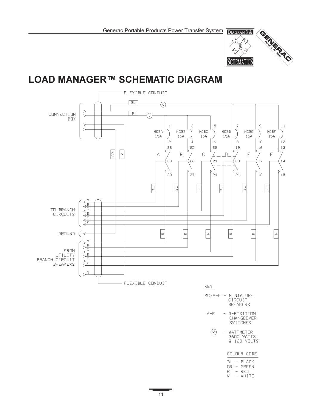
Generac Portable Products Power Transfer System
LOAD MANAGER™ SCHEMATIC DIAGRAM
11
Page 10
Page 12
Page 11
Image 11
Page 10
Page 12
Contents
Description
Generac
Generator Compatibility
Carton Contents
Specifications
Unpacking
Sum Loads from Data Plates
General Safety Information
Plan the Installation
Measure Actual Loads
Load Manager Switch
Installation Procedure
Make Sure
Wire Detached From Breaker
Shows a properly-connected Green lead
Connection Box
Typical Completed Power Transfer System Installation
Connection Box Installation
Identifying Circuits
Connecting Cord Set
Installation and Load Management Notes
Load Manager Schematic Diagram
Description Qty
Exploded View & Parts List
Switch To Generator Power
Operating Procedure
Circuit Breakers in Load Manager Switch
Switch To Utility Power
Testing
Troubleshooting
Generac Portable Products
Limited Warranty
One Year Limited Warranty
Warranty Schedule
Top
Page
Image
Contents