Generac Portable Products Power Transfer System
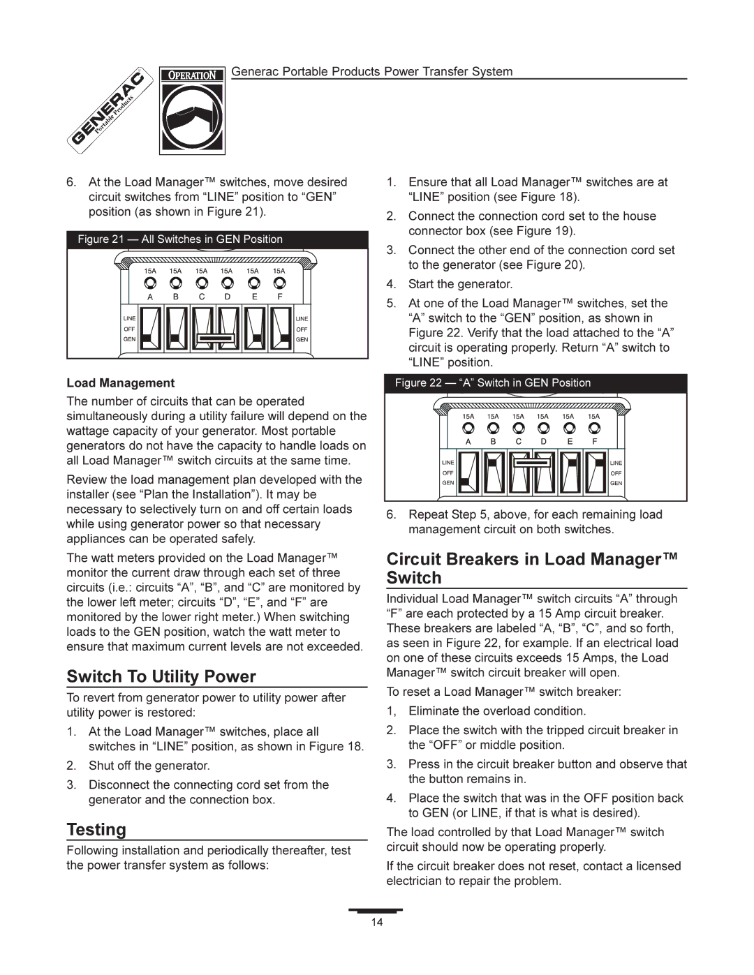
6.At the Load Manager™ switches, move desired circuit switches from “LINE” position to “GEN” position (as shown in Figure 21).
Figure 21 — All Switches in GEN Position
1.Ensure that all Load Manager™ switches are at “LINE” position (see Figure 18).
2.Connect the connection cord set to the house connector box (see Figure 19).
3.Connect the other end of the connection cord set to the generator (see Figure 20).
4.Start the generator.
5.At one of the Load Manager™ switches, set the “A” switch to the “GEN” position, as shown in Figure 22. Verify that the load attached to the “A” circuit is operating properly. Return “A” switch to “LINE” position.
Load Management | Figure 22 — “A” Switch in GEN Position |
|
|
The number of circuits that can be operated simultaneously during a utility failure will depend on the wattage capacity of your generator. Most portable generators do not have the capacity to handle loads on all Load Manager™ switch circuits at the same time.
Review the load management plan developed with the installer (see “Plan the Installation”). It may be necessary to selectively turn on and off certain loads while using generator power so that necessary appliances can be operated safely.
The watt meters provided on the Load Manager™ monitor the current draw through each set of three circuits (i.e.: circuits “A”, “B”, and “C” are monitored by the lower left meter; circuits “D”, “E”, and “F” are monitored by the lower right meter.) When switching loads to the GEN position, watch the watt meter to ensure that maximum current levels are not exceeded.
Switch To Utility Power
To revert from generator power to utility power after utility power is restored:
1.At the Load Manager™ switches, place all switches in “LINE” position, as shown in Figure 18.
2.Shut off the generator.
3.Disconnect the connecting cord set from the generator and the connection box.
Testing
Following installation and periodically thereafter, test the power transfer system as follows:
6.Repeat Step 5, above, for each remaining load management circuit on both switches.
Circuit Breakers in Load Manager™ Switch
Individual Load Manager™ switch circuits “A” through “F” are each protected by a 15 Amp circuit breaker. These breakers are labeled “A, “B”, “C”, and so forth, as seen in Figure 22, for example. If an electrical load on one of these circuits exceeds 15 Amps, the Load Manager™ switch circuit breaker will open.
To reset a Load Manager™ switch breaker:
1, Eliminate the overload condition.
2.Place the switch with the tripped circuit breaker in the “OFF” or middle position.
3.Press in the circuit breaker button and observe that the button remains in.
4.Place the switch that was in the OFF position back to GEN (or LINE, if that is what is desired).
The load controlled by that Load Manager™ switch circuit should now be operating properly.
If the circuit breaker does not reset, contact a licensed electrician to repair the problem.
14