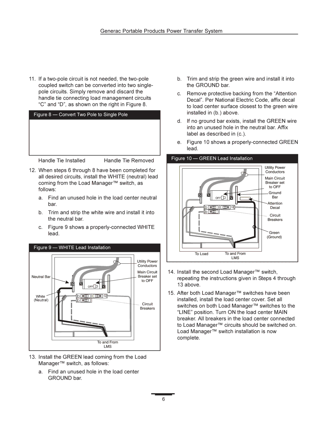
Generac Portable Products Power Transfer System
11.If a
Figure 8 — Convert Two Pole to Single Pole
Handle Tie Installed | Handle Tie Removed |
b.Trim and strip the green wire and install it into the GROUND bar.
c.Remove protective backing from the “Attention Decal”. Per National Electric Code, affix decal to load center surface closest to the green wire installed in (b.) above.
d.If no ground bar exists, install the GREEN wire into an unused hole in the neutral bar. Affix label as described in (c.).
e.Figure 10 shows a properly-connected GREEN lead.
Figure 10 — GREEN Lead Installation
12.When steps 6 through 8 have been completed for all desired circuits, install the WHITE (neutral) lead coming from the Load Manager™ switch, as follows:
a.Find an unused hole in the load center neutral bar.
b.Trim and strip the white wire and install it into the neutral bar.
c.Figure 9 shows a properly-connected WHITE lead.
Figure 9 — WHITE Lead Installation
(Neutral) |
13.Install the GREEN lead coming from the Load Manager™ switch, as follows:
a.Find an unused hole in the load center GROUND bar.
14.Install the second Load Manager™ switch, repeating the instructions given in Steps 4 through 13 above.
15.After both Load Manager™ switches have been installed, install the load center cover. Set all switches on both Load Manager™ switches to the “LINE” position. Turn ON the load center MAIN breaker. All breakers in the load center connected to Load Manager™ circuits should be switched on. Load Manager™ switch installation is now complete.
6
