Generac Portable Products Power Transfer System
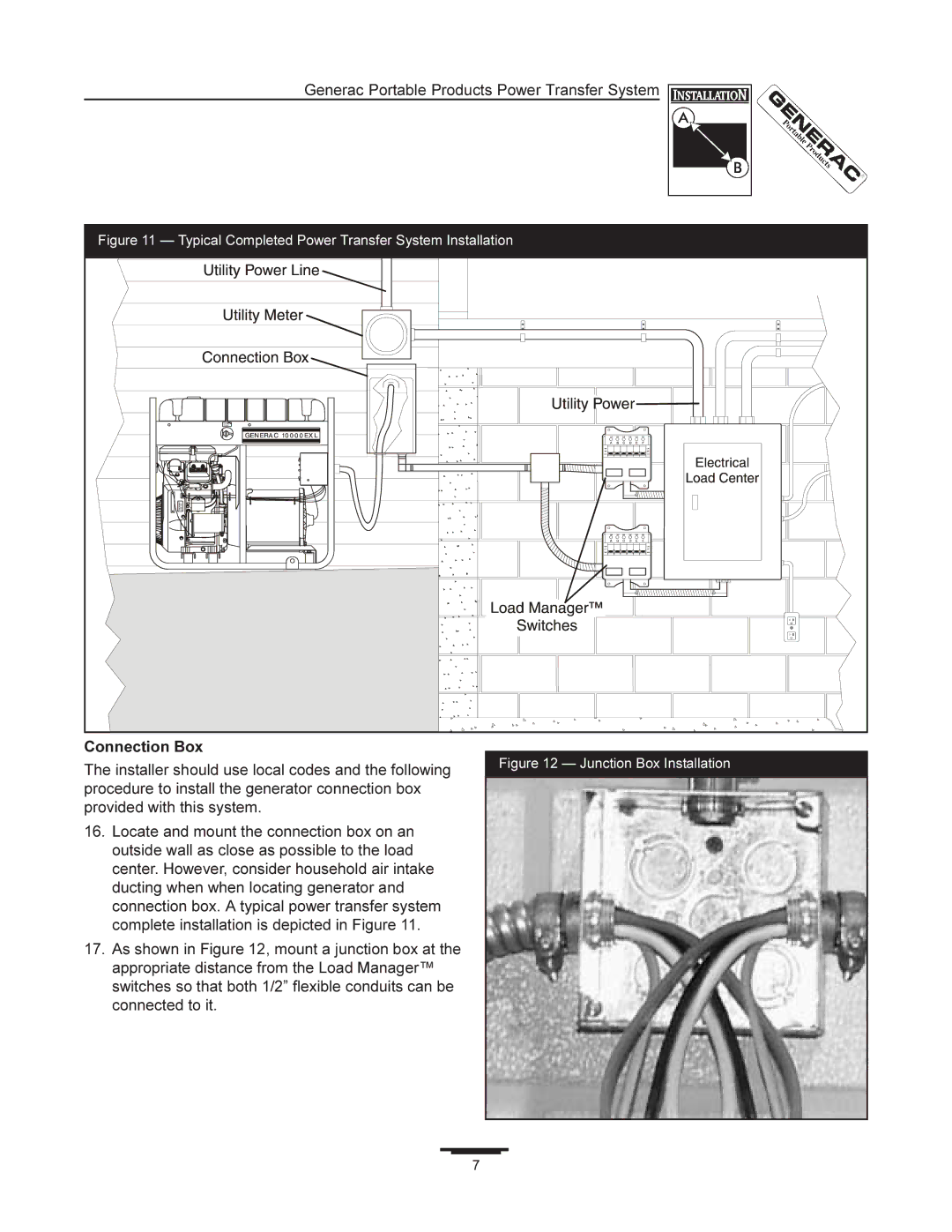
Figure 11 — Typical Completed Power Transfer System Installation
Connection Box
The installer should use local codes and the following | Figure 12 — Junction Box Installation |
| |
procedure to install the generator connection box |
|
provided with this system. |
|
16.Locate and mount the connection box on an outside wall as close as possible to the load center. However, consider household air intake ducting when when locating generator and connection box. A typical power transfer system complete installation is depicted in Figure 11.
17.As shown in Figure 12, mount a junction box at the appropriate distance from the Load Manager™ switches so that both 1/2” flexible conduits can be connected to it.
7