Generac Portable Products Power Transfer System
OPERATING PROCEDURE
This manual section describes the routine procedures used by the owner to operate the Power Transfer system.
Each Load Manager™ switch is equipped with six
Switch To Generator Power
To switch to generator power after a utility power failure:
1.Ensure all Load Manager™ switches are in “LINE” position, as shown in Figure 18.
Figure 18 — Switches in LINE Position
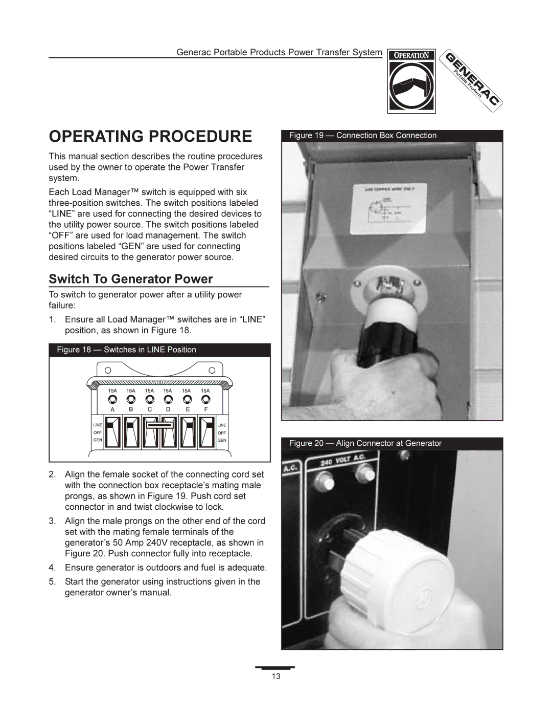
2.Align the female socket of the connecting cord set with the connection box receptacle’s mating male prongs, as shown in Figure 19. Push cord set connector in and twist clockwise to lock.
3.Align the male prongs on the other end of the cord set with the mating female terminals of the generator’s 50 Amp 240V receptacle, as shown in Figure 20. Push connector fully into receptacle.
4.Ensure generator is outdoors and fuel is adequate.
5.Start the generator using instructions given in the generator owner’s manual.
Figure 19 — Connection Box Connection
Figure 20 — Align Connector at Generator
13