Generac Portable Products Power Transfer System
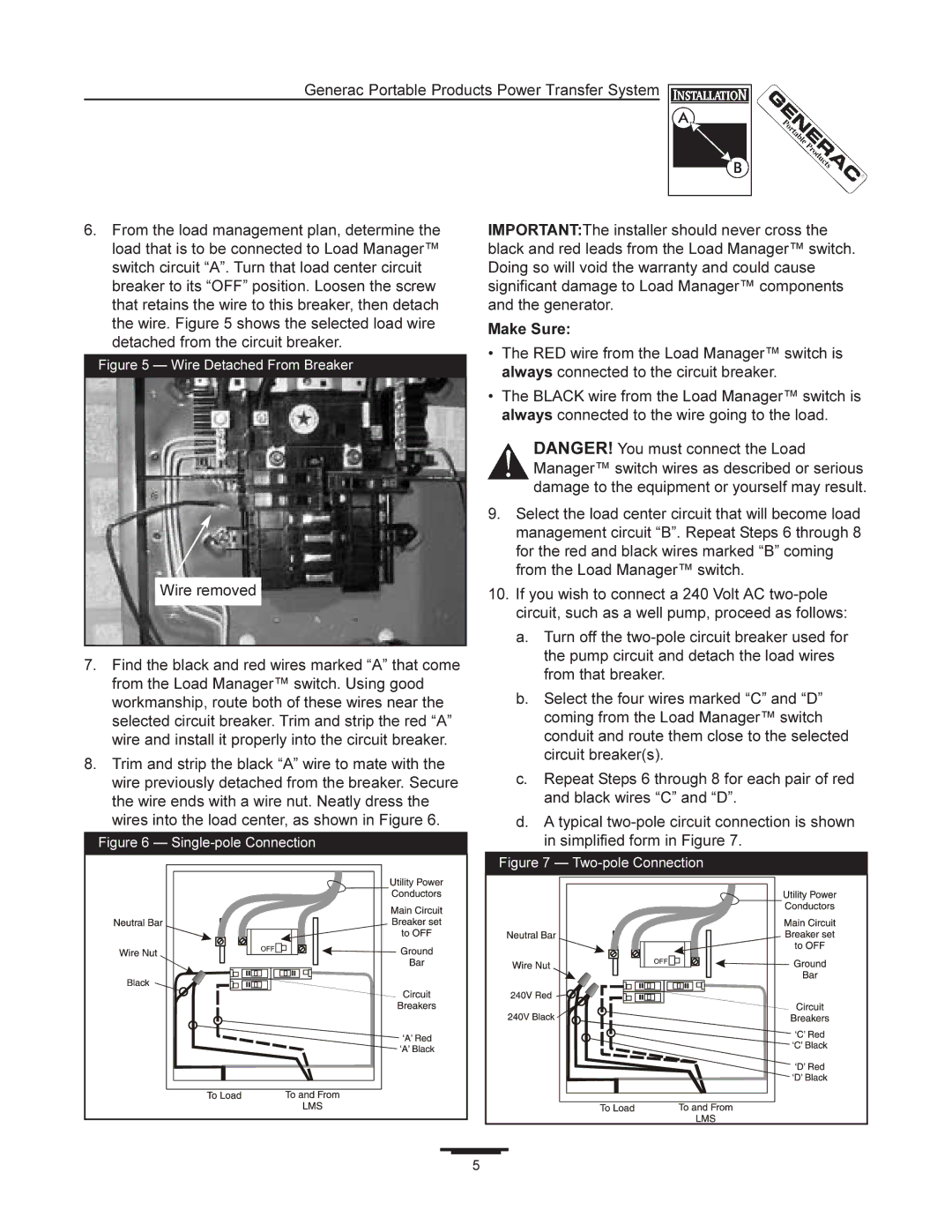
6.From the load management plan, determine the load that is to be connected to Load Manager™ switch circuit “A”. Turn that load center circuit breaker to its “OFF” position. Loosen the screw that retains the wire to this breaker, then detach the wire. Figure 5 shows the selected load wire detached from the circuit breaker.
Figure 5 — Wire Detached From Breaker
Wire removed
7.Find the black and red wires marked “A” that come from the Load Manager™ switch. Using good workmanship, route both of these wires near the selected circuit breaker. Trim and strip the red “A” wire and install it properly into the circuit breaker.
8.Trim and strip the black “A” wire to mate with the wire previously detached from the breaker. Secure the wire ends with a wire nut. Neatly dress the wires into the load center, as shown in Figure 6.
Figure 6 — Single-pole Connection
IMPORTANT:The installer should never cross the black and red leads from the Load Manager™ switch. Doing so will void the warranty and could cause significant damage to Load Manager™ components and the generator.
Make Sure:
•The RED wire from the Load Manager™ switch is always connected to the circuit breaker.
•The BLACK wire from the Load Manager™ switch is always connected to the wire going to the load.
DANGER! You must connect the Load Manager™ switch wires as described or serious damage to the equipment or yourself may result.
9.Select the load center circuit that will become load management circuit “B”. Repeat Steps 6 through 8 for the red and black wires marked “B” coming from the Load Manager™ switch.
10.If you wish to connect a 240 Volt AC
a.Turn off the
b.Select the four wires marked “C” and “D” coming from the Load Manager™ switch conduit and route them close to the selected circuit breaker(s).
c.Repeat Steps 6 through 8 for each pair of red and black wires “C” and “D”.
d.A typical
Figure 7 — Two-pole Connection
5