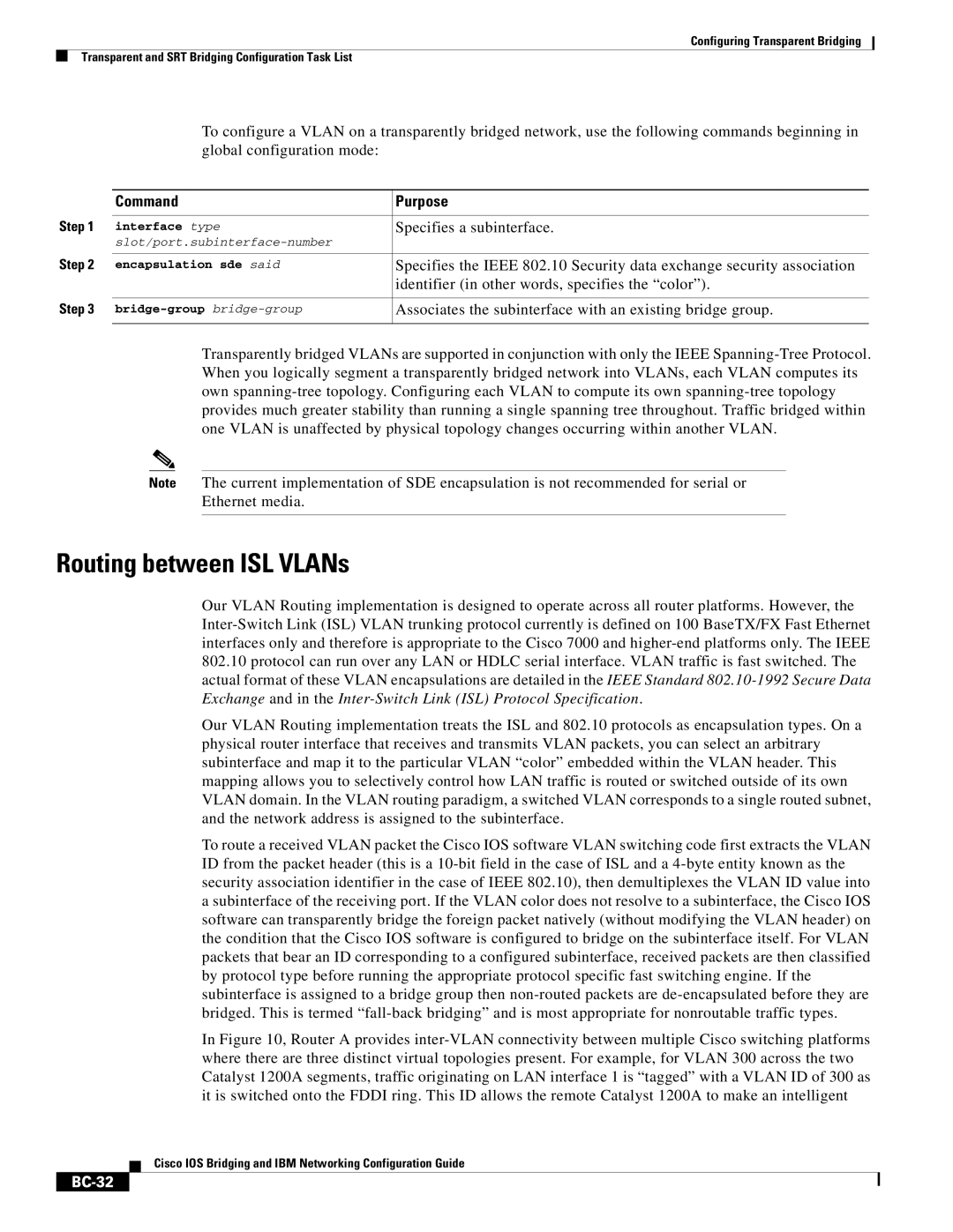
BC-23 specifications
Cisco Systems has long been a leader in the networking industry, and its BC-23 model exemplifies the company's commitment to innovation and performance. Aimed at enhancing business operations, the BC-23 is tailored for organizations looking for robust solutions that support their digital transformation efforts.One of the standout features of the Cisco BC-23 is its advanced networking capabilities. It supports high-speed data transmission, enabling seamless communication across networks. With multi-gigabit Ethernet ports, the BC-23 facilitates faster data rates, accommodating the increasing bandwidth demands of modern applications. This feature is particularly beneficial for businesses that rely heavily on cloud services, video conferencing, and data-heavy applications.
Security is a top priority, and the Cisco BC-23 incorporates cutting-edge security measures. Integrated threat detection and prevention systems help safeguard sensitive data from cyber threats. Additionally, the device supports secure access protocols, ensuring that only authorized users can connect to the network. This multi-layered security approach not only protects the network infrastructure but also secures the integrity of the data being transmitted.
Another significant characteristic of the BC-23 is its support for software-defined networking (SDN). This technology allows businesses to manage their networks through centralized software applications, facilitating real-time adjustments and optimizations. The flexibility afforded by SDN is especially advantageous in dynamic environments where network demands can shift rapidly.
The Cisco BC-23 also offers enhanced management features, allowing IT teams to monitor network performance and analytics effectively. This visibility into network operations enables organizations to identify potential issues before they escalate, minimizing downtime and keeping business processes smooth.
Furthermore, the BC-23 is designed for scalability. As organizations grow, their networking needs evolve, and the BC-23 can easily adapt to these changes. Businesses can add additional devices and capabilities without the need for a complete overhaul of their existing infrastructure.
With its combination of speed, security, and scalability, the Cisco Systems BC-23 is an invaluable asset for modern businesses. It stands out not just as a networking device but as a comprehensive solution that meets the demands of today's fast-paced, technology-driven environment. As companies continue to leverage digital tools for growth and efficiency, the BC-23 will undoubtedly play a significant role in their success.

