Rose electronic 2xE manual Switch Installation Multiple units BUS topology

Models: 2xE

1 84
Download 84 pages 4.97 Kb
Page 20
Image 20

Switch Installation – Multiple units – “BUS” topology

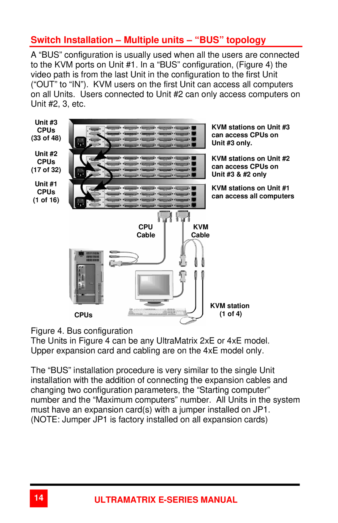
A “BUS” configuration is usually used when all the users are connected to the KVM ports on Unit #1. In a “BUS” configuration, (Figure 4) the video path is from the last Unit in the configuration to the first Unit (“OUT” to “IN”). KVM users on the first Unit can access all computers on all Units. Users connected to Unit #2 can only access computers on Unit #2, 3, etc.

Unit #3

CPUs

(33 of 48)

Unit #2

CPUs

(17 of 32)

Unit #1

CPUs

(1 of 16)

KVM stations on Unit #3 can access CPUs on Unit #3 only.

KVM stations on Unit #2 can access CPUs on Unit #3 & #2 only

KVM stations on Unit #1 can access all computers

CPUKVM

Cable Cable


KVM station

CPUs

(1 of 4)

Figure 4. Bus configuration

The Units in Figure 4 can be any UltraMatrix 2xE or 4xE model. Upper expansion card and cabling are on the 4xE model only.

The “BUS” installation procedure is very similar to the single Unit installation with the addition of connecting the expansion cables and changing two configuration parameters, the “Starting computer” number and the “Maximum computers” number. All Units in the system must have an expansion card(s) with a jumper installed on JP1. (NOTE: Jumper JP1 is factory installed on all expansion cards)

14ULTRAMATRIX E-SERIES MANUAL

Page 20
Image 20
Rose electronic 2xE manual Switch Installation Multiple units BUS topology